Distributed optical fiber equal salt deposit density sensor and sensing method thereof

A technology of distributed optical fiber and sensor

Inactive Publication Date: 2010-08-04
SHANGHAI BOOM FIBER SENSING TECH
View PDF0 Cites 10 Cited by
  • Summary
  • Abstract
  • Description
  • Claims
  • Application Information

AI Technical Summary

Problems solved by technology

[0006] The invention provides a distributed optical fiber salt density sensor and a sensing method to solve the problems that the existing optical fiber salt density sensor cannot be positioned and has low precision

Method used


Image

  • Distributed optical fiber equal salt deposit density sensor and sensing method thereof
  • Distributed optical fiber equal salt deposit density sensor and sensing method thereof

Examples


Embodiment Construction

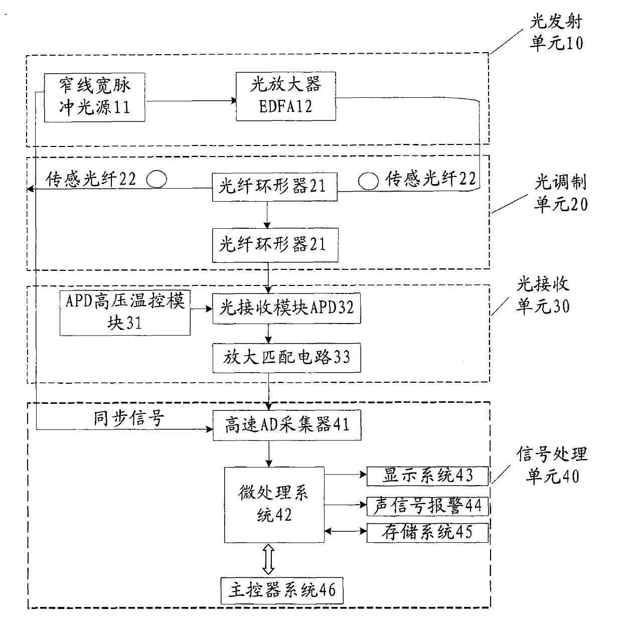
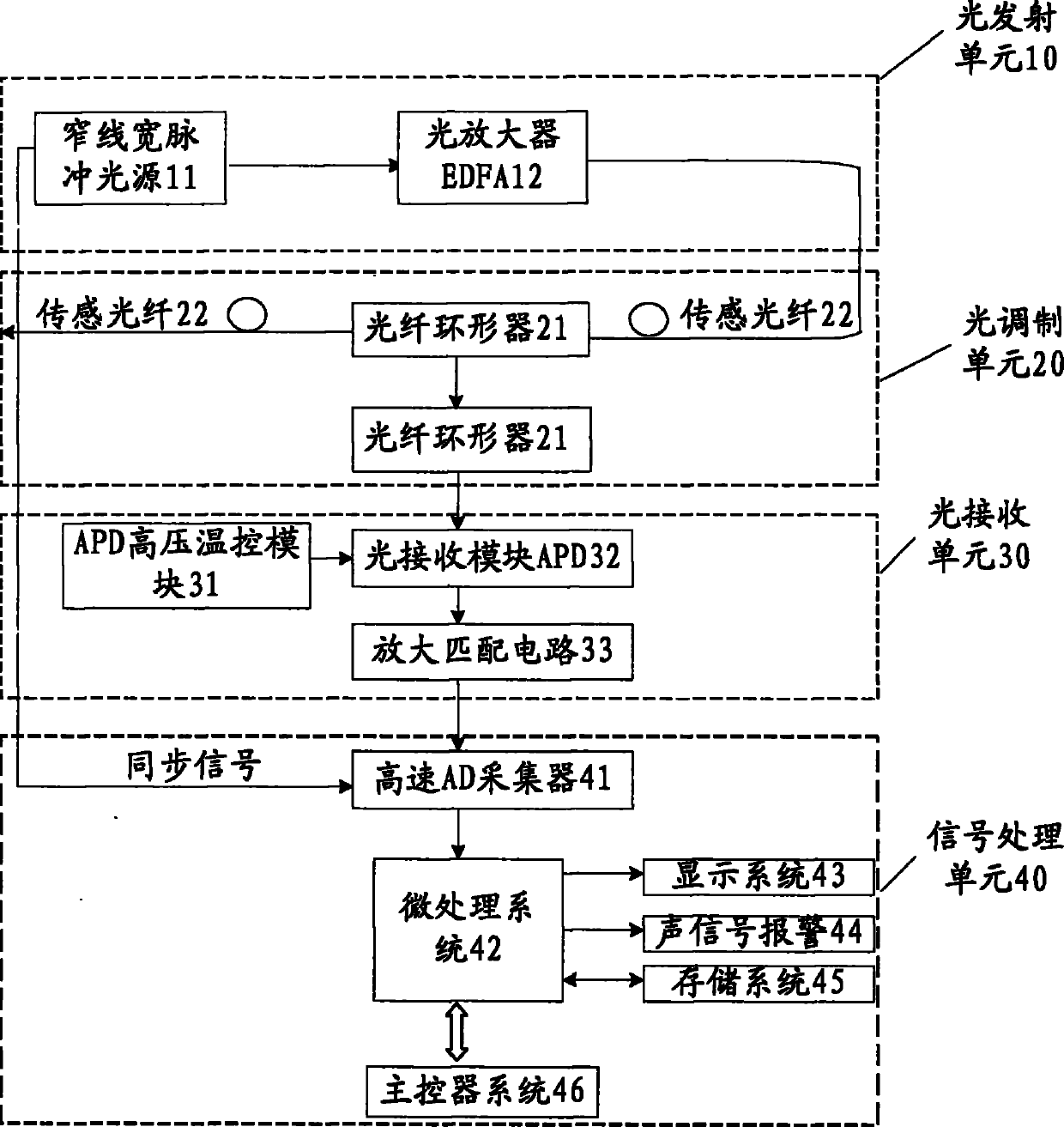
[0033] The distributed optical fiber salt density sensor and sensing method proposed by the present invention will be further described in detail below with reference to the accompanying drawings and specific embodiments. According to the following description and claims, the advantages and features of the present invention will be clearer. It should be noted that the drawings all adopt a very simplified form and all use imprecise ratios, which are only used to conveniently and clearly assist in explaining the purpose of the embodiments of the present invention.

[0034] The core idea of ​​the present invention is to provide a distributed optical fiber salt density sensor and a sensing method. The distributed optical fiber salt density sensor is based on the measurement principle of optical time domain reflection and salt density leading to changes in absorption and scattering loss of optical fiber materials, To measure the nuclear salt density in the target area, the system has ...


PUM

PropertyMeasurementUnit
wavelengthaaaaaaaaaa

Abstract

The invention discloses a distributed optical fiber equal salt deposit density sensor and a sensing method thereof. The distributed optical fiber equal salt deposit density sensor comprises a light transmitting unit, a light modulating unit, a light receiving unit and a signal processing unit; integral information of the equal salt deposit density strength in areas where sensing optical fibers pass can be obtained by using the distributed optical fiber equal salt deposit density sensor according to the invention to perform one measurement, and the sensor has long system monitor range and high positioning accuracy. Simultaneously, the invention further provides a sensing method of the distributed optical fiber equal salt deposit density sensor, which includes simple steps and can conveniently measure the distribution information of the equal salt deposit density strength in target areas.

Description

Technical field [0001] The invention relates to the technical field of optical fiber sensing, in particular to a distributed optical fiber salt density sensor and a sensing method. Background technique [0002] As early as the mid-1960s, the first patents related to optical fiber sensors appeared, which included Fotonic mechanical displacement sensors using beam transmission and ultrasonic sensors using phase modulation. However, in a broader field, namely, optical fiber sensing technology, a series of research was achieved 10 years later. Since then, optical fiber technology has broken through the lingering state and entered an era of rapid development. [0003] The basic principle of the optical fiber sensor is: the light emitted by the light source enters the modulation area through the optical fiber. Under the action of the measured object, the optical properties such as the intensity, wavelength, frequency, phase and polarization state of the light change, making it a modulate...

Claims


Application Information

Patent Timeline
Patent Type & Authority Applications(China)
IPC IPC(8): G01N9/00
Inventor 杨斌皋魏席刚仝芳轩周正仙
Owner SHANGHAI BOOM FIBER SENSING TECH
Why Eureka
Try Eureka