Developing device and image forming device using the same

一种显影装置、图像的技术,应用在应用电荷图形的电记录工艺的设备、应用电荷图形的电记录工艺、电记录术等方向,能够解决调色剂密度不均匀、显影剂搅拌阻碍、降低显影剂流动性等问题,达到促进搅拌的效果

Inactive Publication Date: 2010-08-04
SHARP KK
View PDF2 Cites 8 Cited by
  • Summary
  • Abstract
  • Description
  • Claims
  • Application Information

AI Technical Summary

Problems solved by technology

However, the problem with this configuration is that if the pitch of the helical push screw is made larger, or the rotational speed of the auger is increased in order to increase the conveying speed of the developer, the pressure acting on the developer by the helical blade becomes larger, Causes stress on the developer and thus severely reduces developer flow
[0008] In addition, if in order to reduce the pressure on the developer, a multi-blade screw structure (such as a double helix structure, a triple helix structure, and other arbitrary structures) is used, so that the agitation of the developer in the axial direction of the helical pusher screw is hindered by the helical blades
As a result, there is a problem with this construction that the variation in toner concentration over the length of the helical pusher screw is not equalized, resulting in non-uniform toner density
[0009] In addition, when a conveying member provided with a plurality of discontinuous stirring blades is used to enhance the stirring performance of the developer, there is a problem in this configuration that the flow of the developer is unstable, causing stress on the developer and thus significantly reducing the developer's agitation performance. fluidity

Method used


Image

  • Developing device and image forming device using the same
  • Developing device and image forming device using the same
  • Developing device and image forming device using the same

Examples


no. 1 example

[0049] Specific embodiments for carrying out the present invention will now be described with reference to the accompanying drawings.

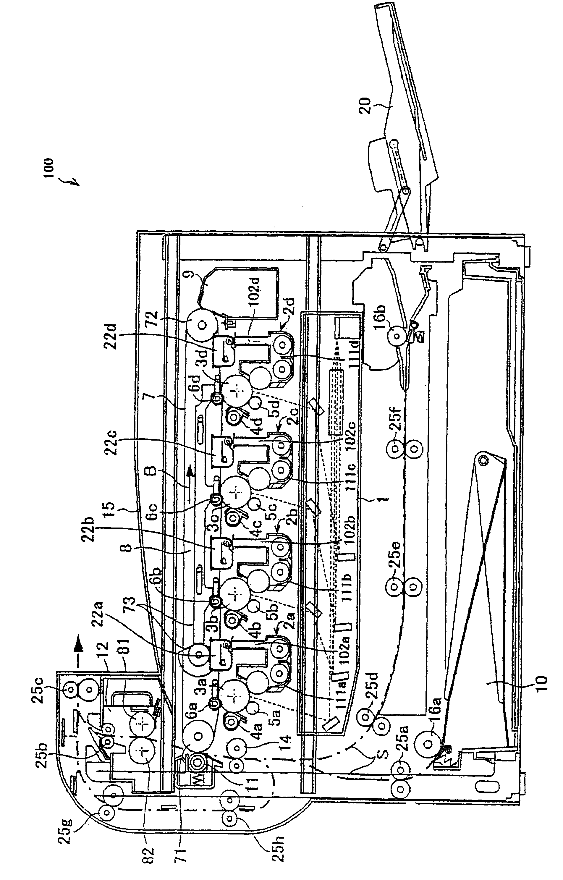
[0050] figure 1 shows an exemplary embodiment of the present invention, and is an explanatory diagram showing the overall configuration of an image forming apparatus in which the developing device

[0051] The image forming apparatus 100 of the present embodiment forms an image using toner based on electrophotography, including: figure 1 As shown, photosensitive drums 3a, 3b, 3c, and 3d for forming electrostatic latent images on their surfaces (in general description, may also be referred to as "photosensitive drums 3"); Chargers (charging devices) 5a, 5b, 5c, and 5d (in general description, may also be referred to as "charger 5"); for forming an electrostatic latent image on the surface of the photosensitive drum 3 exposure unit (exposure device ) 1; developing devices 2a, 2b, 2c, and 2d for supplying toner to the electrostatic latent imag...

no. 2 example

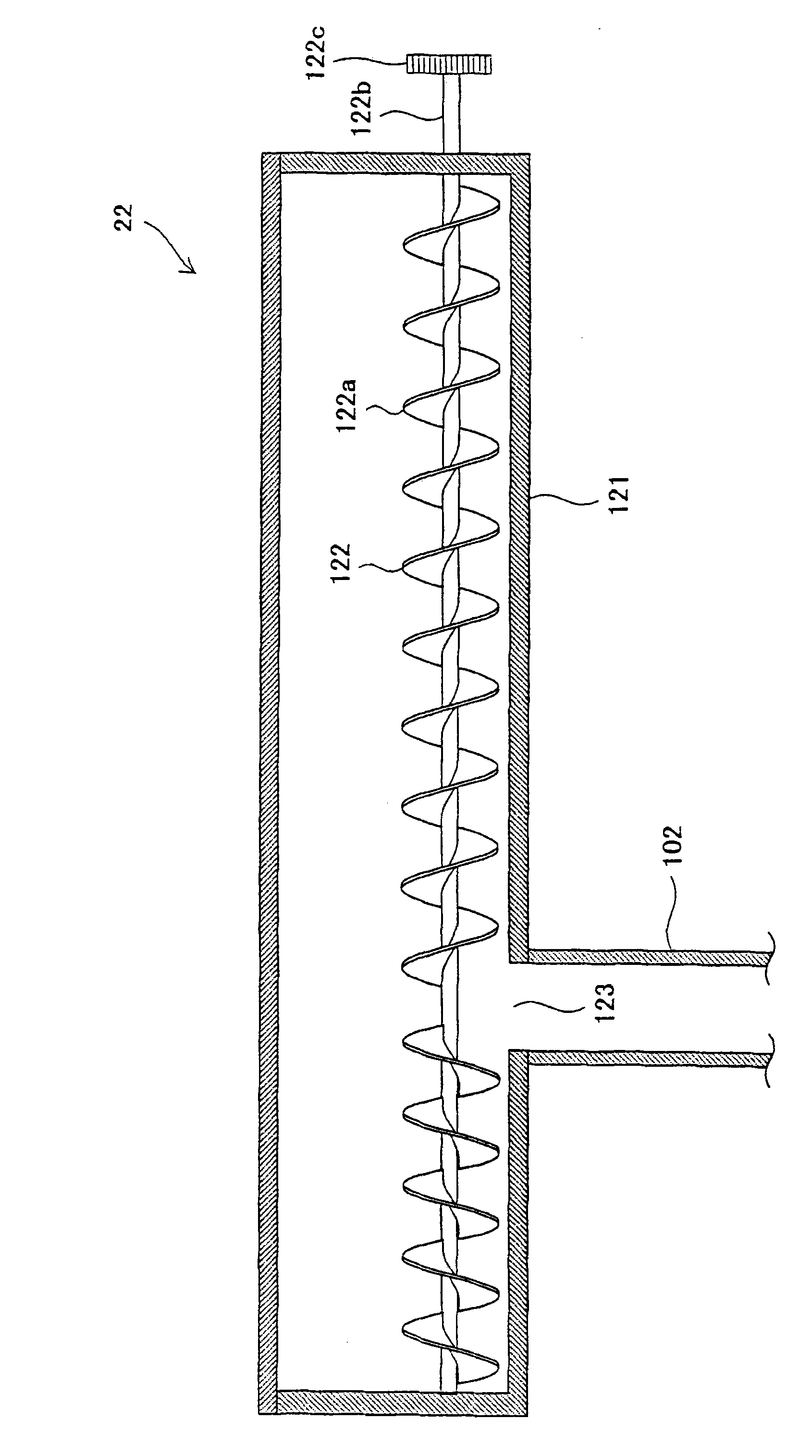
[0142] A developing device 2X according to a second embodiment will be described below with reference to the drawings.

[0143] Figure 8 is a sectional view showing the configuration of the developing device 2X, Figure 9 is along Figure 8 A sectional view taken on plane A3-A4 in , and Figure 10 is along Figure 8 Sectional view taken on plane B3-B4 in .

[0144] Such as Figure 8 As shown, the developing device 2X has a developing roller 114 disposed in a developing tank 111 opposite to the photosensitive drum 3 , and supplies toner from the developing roller 114 to the surface of the photosensitive drum 3 so that static electricity formed on the surface of the photosensitive drum 3 The latent image is visible (developed).

[0145] In addition to the developing roller 114, the developing device 2X includes a developing tank 111, a developing tank cover 115, a toner supply port 115a, a doctor blade 116, a first conveying member 112X, a second conveying member 113X, a ...

no. 3 example

[0173] Next, a third embodiment for realizing the present invention will be described with reference to the drawings.

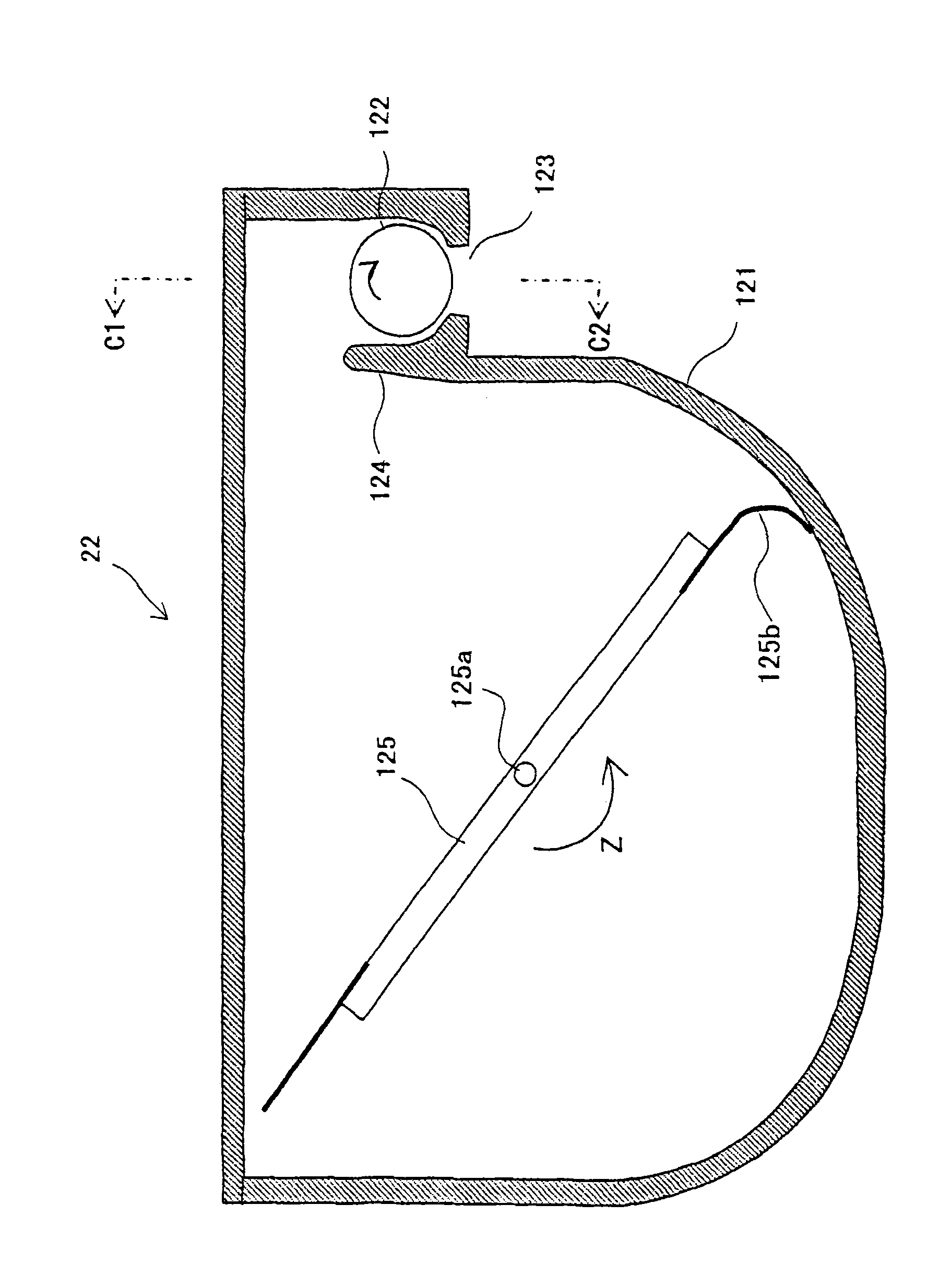
[0174] Figure 11 is an explanatory diagram showing the configuration of a developing device 2Y according to a third embodiment of the present invention.

[0175] Here, since the configuration of the developing device 2Y includes the same components as those of the developing devices 2 and 2X of the first and second embodiments except for the first conveying member and the second conveying member, the same reference numerals are given to the same components, And descriptions of these components are omitted.

[0176] Such as Figure 11 As shown, the developing device 2Y has a developing roller 114 disposed in a developing tank 111 opposite to the photosensitive drum 3 , and supplies toner from the developing roller 114 to the surface of the photosensitive drum 3 so that static electricity formed on the surface of the photosensitive drum 3 The latent image i...


PUM


Abstract

The present invention relates to a developing device and an image forming device using the same. The developing device includes a developing vessel for storing a developer, a first conveying passage, a second conveying passage, a first conveying member, a second conveying member and a developing roller for supplying toner to a photoreceptor drum. The first conveying member has a first rotary shaft and a first conveying blade formed on the periphery of the first rotary shaft. The first conveying blade has a large-diametric ring-shaped helical blade and a small-diametric helical blade, forming a double-helical structure. Alternatively, the first conveying blade is formed of helical blades being different in phase; each helical blade is formed so that the radius varies on a cycle of the rotational angle of 180 degrees.

Description

technical field [0001] The present invention relates to a developing device and an image forming apparatus using the developing device, and more particularly to a developing device using a two-component developer containing toner and a magnetic carrier and image forming apparatus using the developing device As an apparatus, the above-described developing device is used in an image forming apparatus for forming an image using toner based on electrophotography, such as an electrophotographic copier, a laser printer, a facsimile machine, and the like. Background technique [0002] In general, image forming apparatuses based on electrophotography, such as copiers, printers, facsimile machines, etc., are known. An image forming apparatus using electrophotographic copying is configured to develop an electrostatic latent image by forming an electrostatic latent image on the surface of a photosensitive drum (toned image carrier), supplying toner from a developing device to the photo...

Claims


Application Information

Patent Timeline
Patent Type & Authority Applications(China)
IPC IPC(8): G03G15/08G03G15/00
CPCG03G2215/0833G03G15/0834G03G2215/0822G03G2215/0838G03G15/0868G03G15/0875G03G15/0879G03G15/0893
Inventor 见原幸一大越俊秀
Owner SHARP KK
Why Eureka
Try Eureka