Airflow headgear for a welding helmet

A technology for welding helmets and helmets, applied in the field of airflow systems, can solve the problems of heavy, inconvenient, and expensive equipment.

Inactive Publication Date: 2010-08-04
ILLINOIS TOOL WORKS INC
View PDF0 Cites 21 Cited by
  • Summary
  • Abstract
  • Description
  • Claims
  • Application Information

AI Technical Summary

Problems solved by technology

However, past attempts have often required separate devices that can be expensive, inconvenient, uncomfortable and / or heavy
For example, a welder may not have time to attach additional equipment that is separate from the welder's current equipment

Method used


Image

  • Airflow headgear for a welding helmet
  • Airflow headgear for a welding helmet
  • Airflow headgear for a welding helmet

Examples


Embodiment Construction

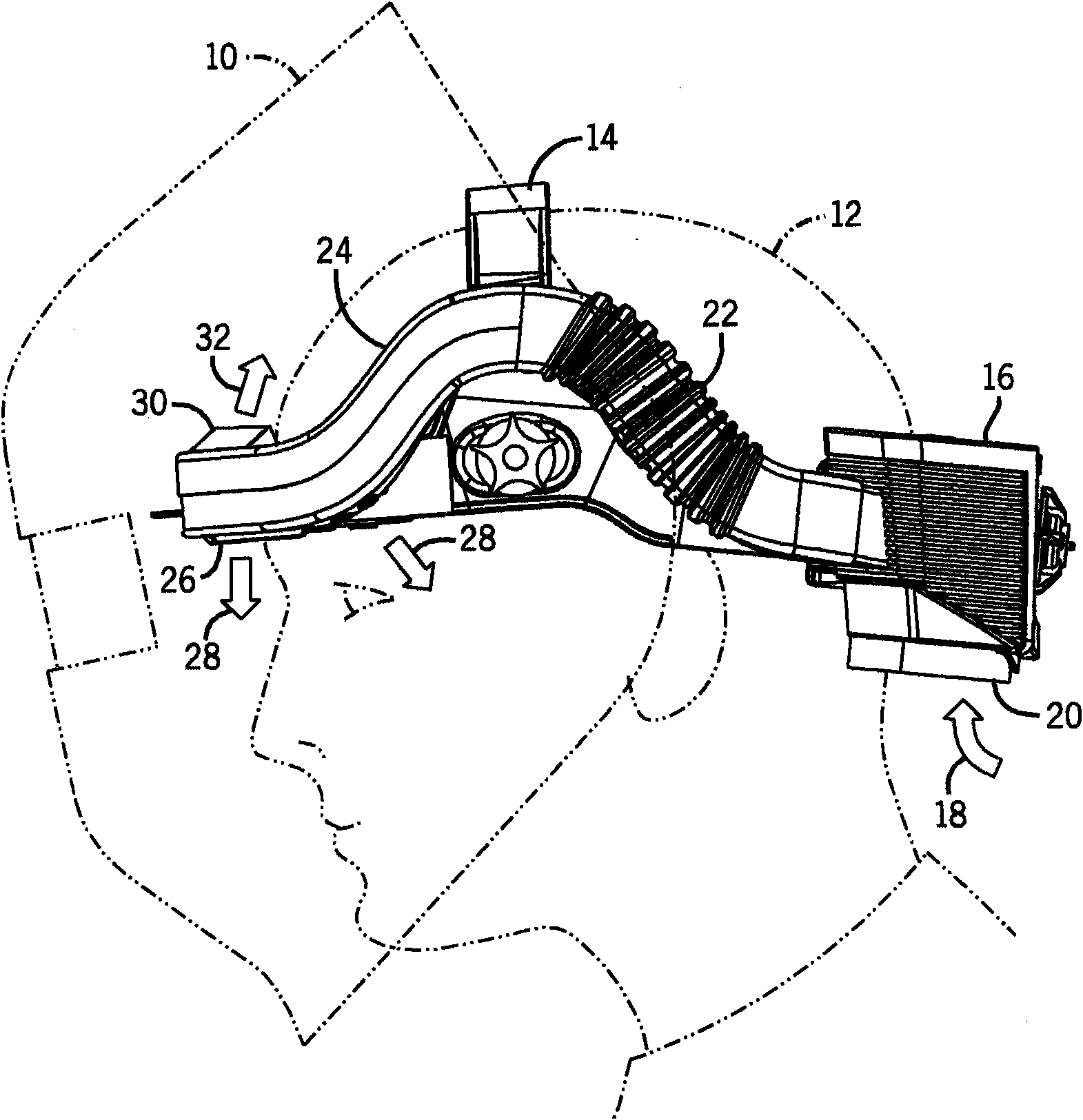
[0022] figure 1 An example welding helmet 10 including an integrated airflow system according to the present invention is shown. The welding helmet 10 may be constructed of thermoplastic resin and may shield the welder's face. The welding helmet 10 may be attached to a headgear 14 worn by a welder or user 12 . Headgear 14 typically includes a strap that extends around the user's head and onto the top of the head to provide support and stability for welding helmet 10 . The airflow system 16 may be attached or integrated to the headgear 14 and generally along the circumference of the headgear 14 . In certain embodiments, the airflow system may be permanently attached to the headgear. In such embodiments, the headgear itself acts as part of the air duct. However, in other embodiments, the airflow system may be secured to the headgear using mounting brackets or other attachment methods. By generally following the circumference of the headgear 14, the airflow system 16 may be ...


PUM


Abstract

An airflow system is provided for a welding helmet. The airflow system includes an air intake (16) with a filter, a blower, and a battery mounted to the rear of headgear for a welding helmet. A manifold wraps around the side and front of the headgear and directs air from the- blower to the front of the headgear. The manifold includes a lower vent (26) for directing air onto a user's face and an upper vent (30) for directing air over a user's head toward the rear of the headgear. The vents are intended to create positive pressure to impede the entry of unfiltered air into the user's breathing zone. The manifold further includes a portion of flexible tubing (22) for adjusting the size of the airflow system in conjunction with adjustment of the headgear diameter. The airflow system generally conforms to the structure and shape of the headgear to maintain a location close to the user's head.

Description

[0001] Cross References to Related Applications [0002] This application is a non-provisional patent application of US Provisional Patent Application No. 60 / 967,511, entitled "Airflow Headgear for a Welding Helmet," filed September 5, 2007, the entire contents of which are hereby incorporated by reference. technical field [0003] The present invention generally relates to airflow systems for welding helmets. Background technique [0004] Welding can be a heat-intensive process, especially outdoors in the summer months or in factories without air conditioning. Additionally, welders typically wear equipment such as leather gloves, long-sleeved jackets, and welding helmets to shield the eyes, face, and neck. The equipment increases the heat concentration of the welding process and reduces comfort due to the lack of air flow, especially around the welder's face. In addition, the welding process can produce fumes, fumes, and various gases that increase discomfort for the weld...

Claims


Application Information

Patent Timeline
Patent Type & Authority Applications(China)
IPC IPC(8): A61F9/06
CPCA61F9/068A62B18/003A62B18/006A62B18/04
Inventor 威廉·贝克尔肯尼斯·S·多布森郭钜钊埃里克·萨默斯
Owner ILLINOIS TOOL WORKS INC
Why Eureka
Try Eureka