Exercising system with display function
A motion system and display function technology, applied in the field of motion system, can solve problems such as boredom
- Summary
- Abstract
- Description
- Claims
- Application Information
AI Technical Summary
Problems solved by technology
Method used
Image
Examples
Embodiment approach 1
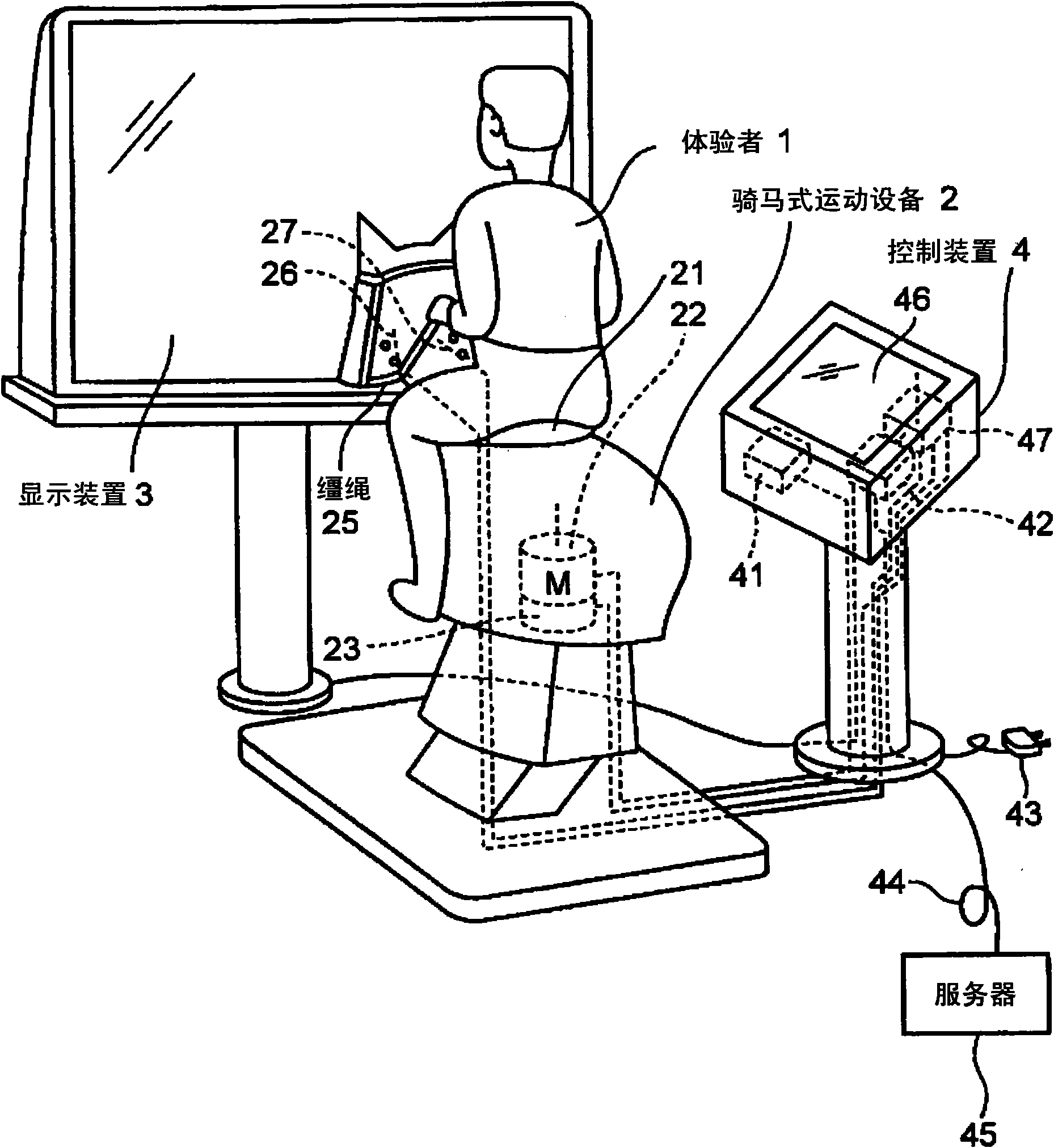
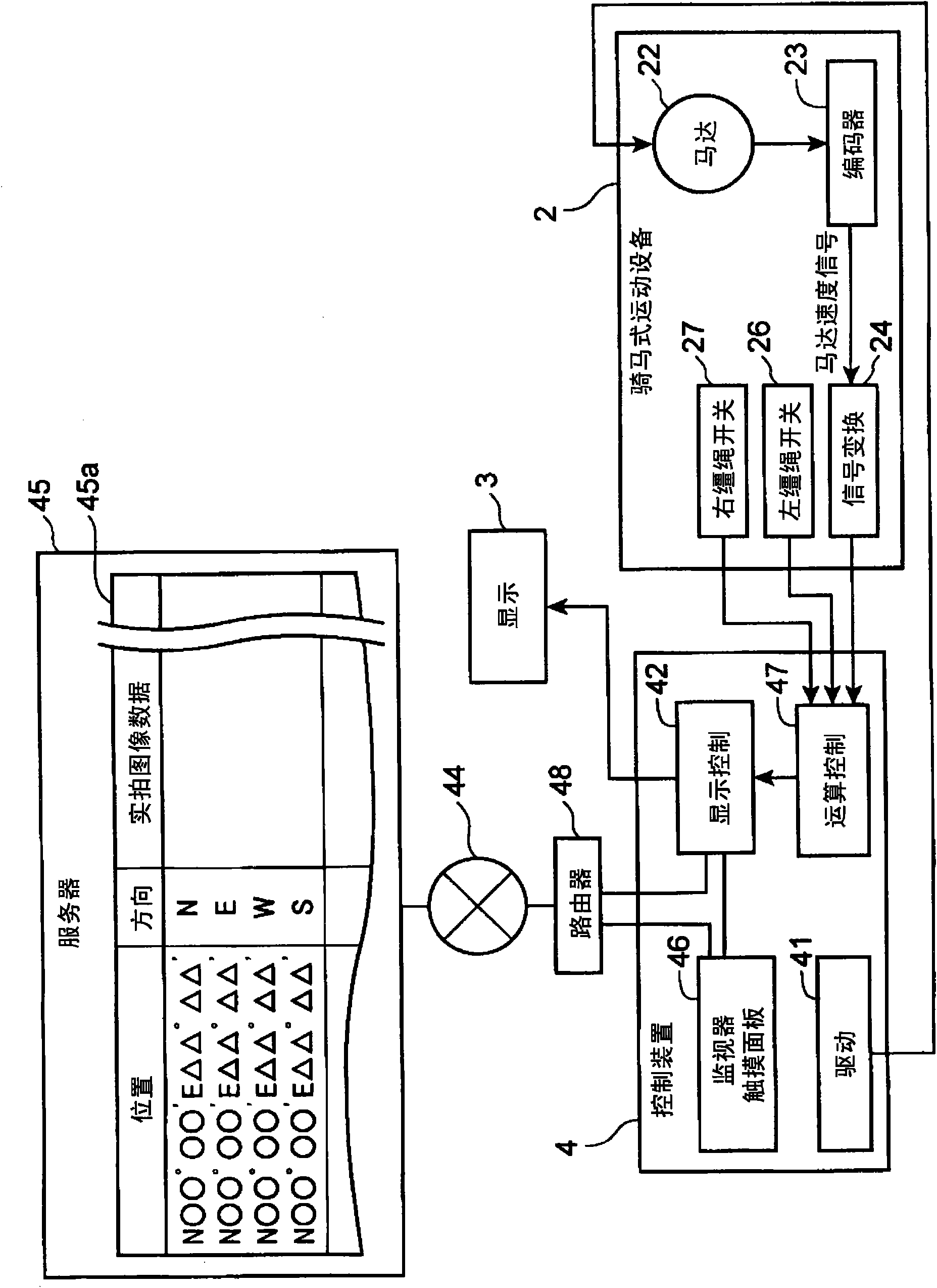
[0069] figure 1 It is a perspective view which shows the whole structure of the exercise system concerning one embodiment of this invention. This exercise system is equipped with the exercise equipment that the experiencer 1 exercises, that is, the horse-riding exercise equipment 2, the display device 3, and the scenery image that drives the above-mentioned horse-riding exercise equipment 2 and changes in conjunction with the driving, that is, the exercise of the above-mentioned experiencer 1. A motion system with a display function constituted by a control device 4 displayed on the above-mentioned display device 3 .
[0070] The above-mentioned equestrian exercise equipment 2 is a device that applies an exercise load to the experiencer 1 by swinging the seat 21, and the rotation of the motor 22 may be changed by using gears, links, levers, etc. not shown in the figure to change the swing of the seat 21. Alternatively, as in Patent Document 4 above, a plurality of hydraulic o...
Embodiment approach 2
[0086] Figure 9 is a block diagram showing the electrical configuration of a motion system according to another embodiment of the present invention. Should Figure 9 The structure shown is the same as the above figure 2 The shown configurations are similar, and corresponding parts are given the same reference numerals and their descriptions are omitted. It should be noted that in this embodiment, a personal computer 51 is used instead of the above-described large-sized display device 3 and control device 4 . Correspondingly, the horse-riding exercise equipment 2 a is constituted by a conventional single product, and the motor 22 is driven by a built-in drive circuit 28 . However, the encoder 23, the signal conversion circuit 24, and the switches 26 and 27 are provided as detection means, and the motor speed signal from the signal conversion circuit 24 and the rein operation signal from the switches 26 and 27 are converted into corresponding ones through the interface 29, ...
Embodiment approach 3
[0090] Figure 10 It is a block diagram showing an electrical configuration of a motion system according to yet another embodiment of the present invention. Should Figure 10 The structure shown is similar to the above Figure 9 In the shown structure, the same code|symbol is attached|subjected to the corresponding part, and the description is abbreviate|omitted. Note that, in this embodiment, a DVD recorder (recorder) 61 is used instead of the control device 4 described above. Corresponding to this, in the equestrian type exercise equipment 2b, instead of the interface 29 in the above-mentioned equestrian type exercise equipment 2a, a remote control signal conversion circuit 69 is set, and the remote control signal conversion circuit 69 is the same as the existing remote controller 68. The recorder 61 sends a signal.
[0091] On the other hand, on the side of the above-mentioned DVD recorder 61, a display control circuit 62 corresponding to the above-mentioned display con...
PUM
 Abstract
Description
Claims
Application Information
 - R&D
- Intellectual Property
- Life Sciences
- Materials
- Tech Scout
- Unparalleled Data Quality
- Higher Quality Content
- 60% Fewer Hallucinations
Browse by: Latest US Patents, China's latest patents, Technical Efficacy Thesaurus, Application Domain, Technology Topic, Popular Technical Reports.
© 2025 PatSnap. All rights reserved.Legal|Privacy policy|Modern Slavery Act Transparency Statement|Sitemap|About US| Contact US: help@patsnap.com


