Rubber injection mold

A rubber injection and mold technology, applied in the field of molds, can solve problems such as low efficiency and high power consumption, and achieve the effects of fast glue feeding, low power consumption, and improved efficiency

Inactive Publication Date: 2010-08-11
衡阳华胜精密模具有限公司
View PDF2 Cites 3 Cited by
  • Summary
  • Abstract
  • Description
  • Claims
  • Application Information

AI Technical Summary

Problems solved by technology

[0003] The purpose of the present invention is to overcome the above-mentioned deficiencies of the prior art, and provide a rubber injection mold to solve the problems of low efficiency and high power consumption caused by the limitation of the number and position of injection points in the existing rubber injection mold

Method used


Image

  • Rubber injection mold
  • Rubber injection mold
  • Rubber injection mold

Examples


Embodiment Construction

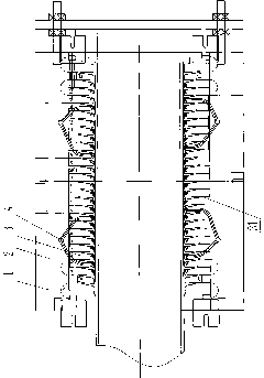
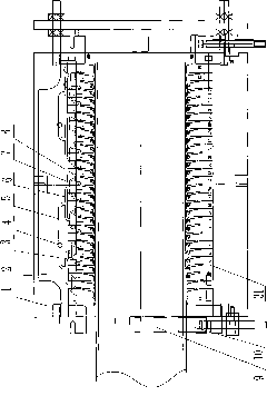
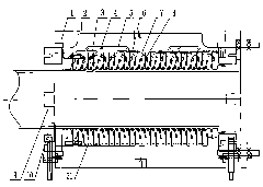
[0012] Such as figure 2 As shown, the rubber injection mold of the present invention includes a mold frame 1, a runner plate 2 and an insert 3 forming an umbrella page, the runner plate 2 and the insert 3 are installed on the mold frame 1, and the runner plate 2 has a glue inlet , there are glue inlets 4 on the glue inlet, each glue inlet 4 corresponds to two primary glue inlets 5, each primary glue inlet 5 corresponds to two secondary glue inlets 6, each secondary glue inlet Lane 6 corresponds to two three-stage glue inlets 7, each three-stage glue inlet 7 corresponds to two four-stage glue inlets 8, each four-stage glue inlet 8 corresponds to an insert 3 forming an umbrella page, and the mold frame 1 is also provided with a lower support 9 and a side support 10, and an exhaust groove 31 is arranged on the insert 3.

[0013] The working principle and application method of the present invention are as follows: the rubber material is injected to the parting surface of the mol...


PUM


Abstract

The invention discloses a rubber injection mold. The rubber injection mold comprises a mold frame 1, a flow channel plate 2 and an insert 3 which forms corrugation, wherein the flow channel plate 2 and the insert 3 are arranged on the mold frame 1; the flow channel plate 2 is provided with a rubber inlet channel; the rubber inlet channel is provided with a rubber inlet 4; each rubber inlet 4 corresponds to two one-stage rubber inlet channels 5; each one-stage rubber inlet channel 5 corresponds to two two-stage rubber inlet channels 6; each two-stage rubber inlet channel 6 corresponds to two three-stage rubber inlet channels 7; each three-stage rubber inlet channel 7 corresponds to two four-stage rubber inlet channels 8; each four-stage rubber inlet channel 8 corresponds to one insert 3 which forms the corrugation; the mold frame 1 is also provided with a lower support 9 and a side support 10; and the insert 3 is provided with an air discharge groove 31. The rubber injection mold has the characteristics of high rubber inlet speed, good air discharge effect, short molding time, high production efficiency, low power consumption and the like, wherein the injection time is only about 3 minutes; because the injection time is very short, the injection can be performed directly at the vulcanizing temperature of about 160 DEG C; and therefore, the injection time and cooling time can be saved, energy consumption is saved by about 50 KW, and efficiency is improved by 50 percent.

Description

technical field [0001] The invention relates to a mold for industrial production, in particular to a rubber injection mold for producing hollow insulators for high-voltage power transmission and transformation. Background technique [0002] In the prior art, the structure of the rubber injection mold for producing high-voltage power transmission and transformation hollow insulators is as follows: figure 1 As shown, it includes a mold frame 1, a runner plate 2 and an insert 3 forming an umbrella page. The runner plate 2 and the insert 3 are installed on the mold frame 1. There is a glue inlet on the runner plate 2, and the glue inlet There are glue inlets 4, and each glue inlet corresponds to a plurality of inserts 3 that form umbrella pages. There are exhaust grooves 31 on the inserts 3, and there are only four or eight glue inlets on the entire mold. The rubber injection mold with this structure can only be injected at about 120°C due to the limitation of the number and po...

Claims


Application Information

Patent Timeline
Patent Type & Authority Applications(China)
IPC IPC(8): B29C45/26
Inventor 阎胜永
Owner 衡阳华胜精密模具有限公司
Why Eureka
Try Eureka