

Plasma reaction chamber for realizing fast reaction gas switching and method thereof
A plasma and reactive gas technology, applied to electrical components, discharge tubes, circuits, etc., can solve the problems of reactive gas waste, reduce deep reaction etching rate, and long switching time, so as to improve stability and reduce Volume, the effect of increasing the switching rate
- Summary
- Abstract
- Description
- Claims
- Application Information
AI Technical Summary
Problems solved by technology
Method used
Image

Examples
Embodiment Construction
[0023] In order to make the object, technical solution and advantages of the present invention clearer, the present invention will be further described in detail below in conjunction with the accompanying drawings.
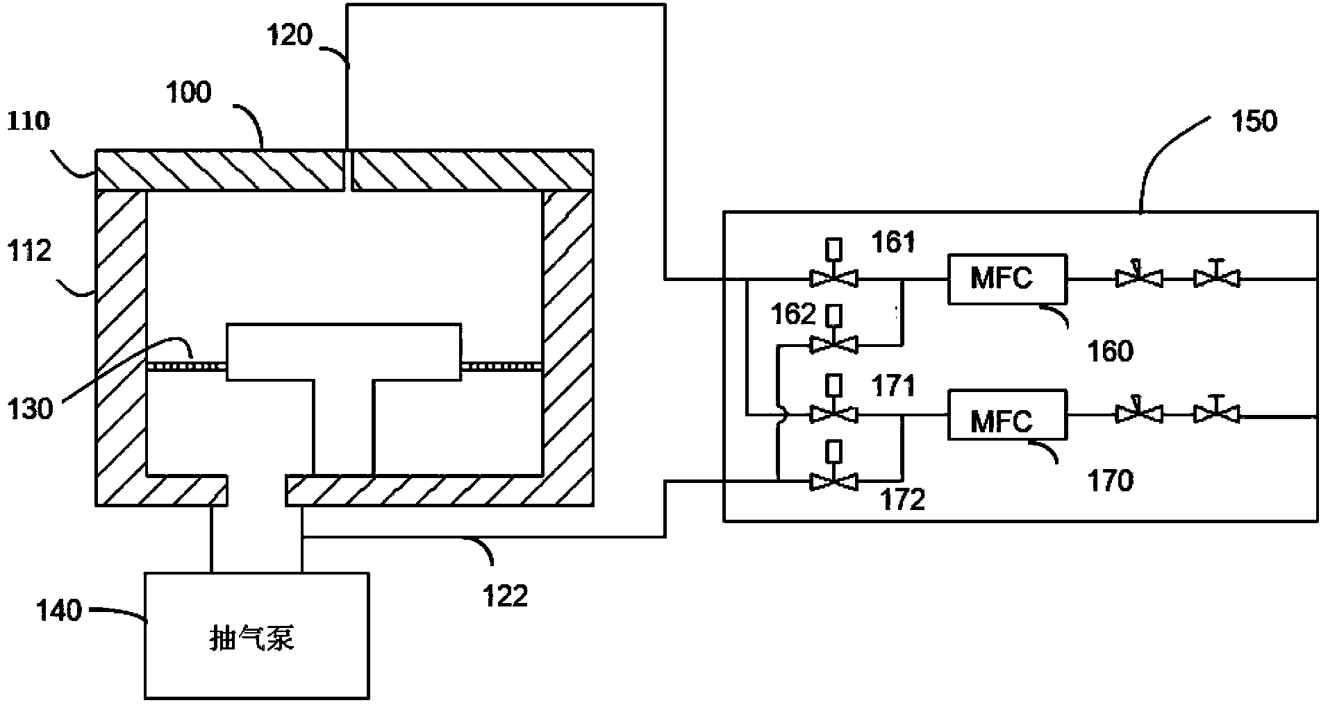
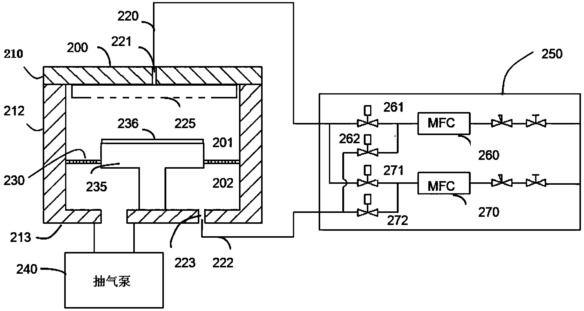
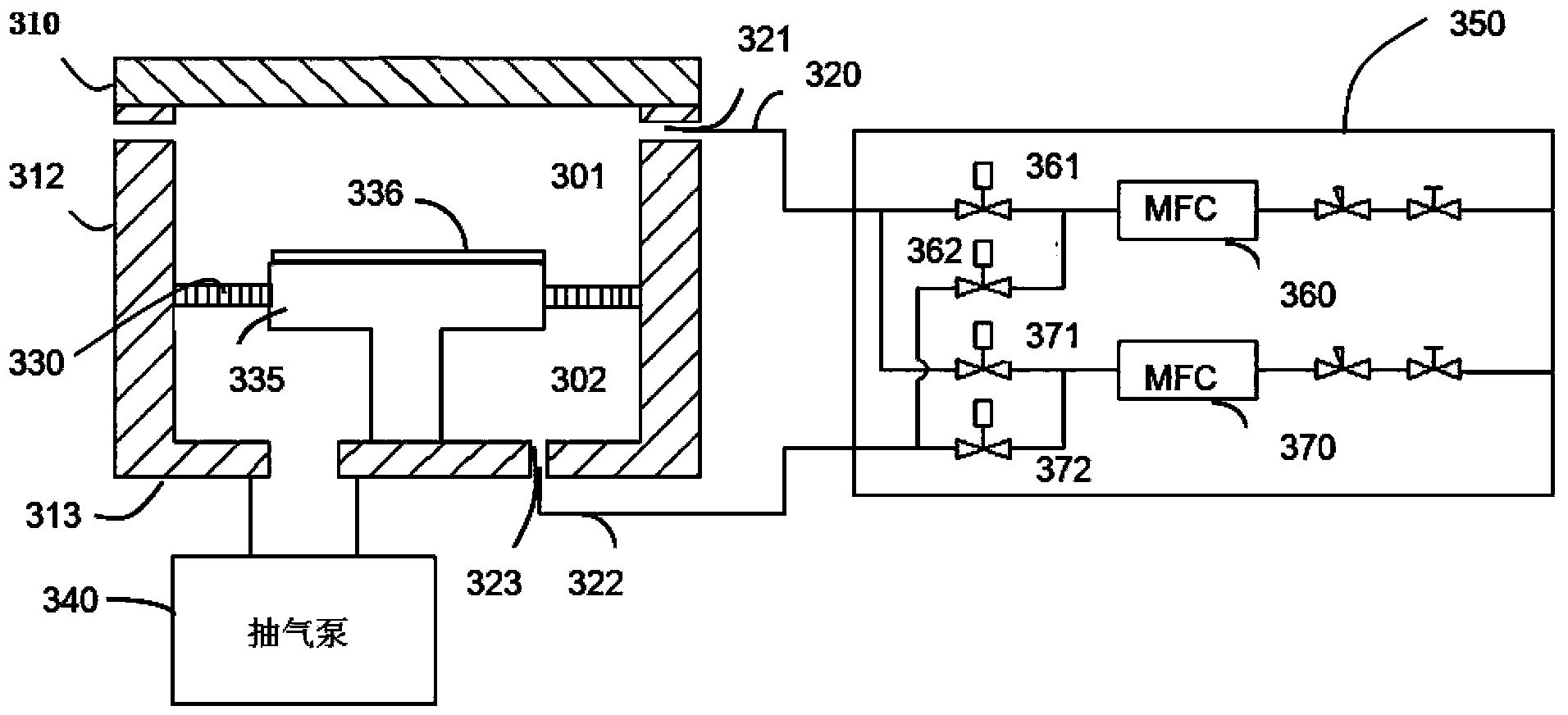
[0024] figure 2 A schematic structural view showing the connection between the plasma reaction chamber and the gas supply system of the present invention, the plasma reaction chamber includes a reaction chamber 200, the reaction chamber 200 includes a substantially cylindrical side wall 212, and a The top plate 210 and the bottom plate 213 located below the side wall 212 . The reaction chamber also includes a base 235 for supporting the substrate 236 , and a confinement ring 230 is arranged around the substrate 236 to divide the reaction chamber 200 into a space 201 above the reaction chamber and a space 202 below the reaction chamber. An air inlet 221 is provided on the top plate 210, and an air inlet pipe 220 is connected to the gas supply system 250 to inject...
PUM
| Property | Measurement | Unit |
|---|---|---|
| The inside diameter of | aaaaa | aaaaa |
Abstract
Description
Claims
Application Information