Intelligent vibration monitor system

A vibration monitoring system, intelligent technology, applied to measuring devices, measuring ultrasonic/sonic/infrasonic waves, instruments, etc., can solve the problems of large fluctuation range of vibration signal amplitude, indistinguishability, and inability to obtain key data, etc., to achieve high sensitivity and Effects of test accuracy, improvement of sensitivity and test accuracy, and simplified measurement operations

Inactive Publication Date: 2010-08-11
四川拓普测控科技有限公司
View PDF8 Cites 15 Cited by
  • Summary
  • Abstract
  • Description
  • Claims
  • Application Information

AI Technical Summary

Problems solved by technology

However, during on-site testing, it is often impossible to accurately estimate the magnitude of the vibration signal in advance, so it is impossible to ensure accurate setting of the range; it may be that the amplitude fluctuation range of the vibration signal is too large, resulting in signal over-range amplitude distortion, or the signal is too small, resulting in the inability to Identification and Data Processing
As a result, the test fails, the key data cannot be obtained, and it may cause a large test loss

Method used


Image

  • Intelligent vibration monitor system
  • Intelligent vibration monitor system
  • Intelligent vibration monitor system

Examples


Embodiment Construction

[0045] The present invention will be described in detail below in conjunction with the accompanying drawings and with the best embodiment.

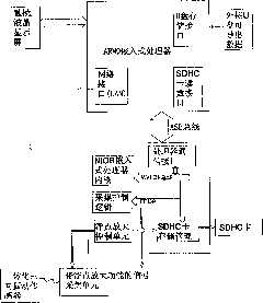
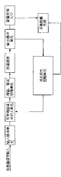
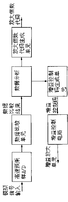
[0046] refer to figure 1 , first of all, the working principle of the whole instrument of the intelligent vibration monitoring system is explained: the vibration signal generated at the test site is picked up by the three-way sensor arranged on site, and converted into an electrical signal that can be collected by the vibrometer. The electrical signal passes through the signal acquisition unit of the vibrometer, and is converted into a digital signal recognizable by the computer under the control of the acquisition control logic. The signal acquisition unit is designed to realize the basic circuit of the floating-point amplification function. During this process, the floating-point amplification control logic compares and analyzes the signals, and continuously sends gain control codes to the signal acquisition unit, so that the signal acq...


PUM


Abstract

An intelligent vibration monitor system relates to the field test, record and analysis system of vibration signals. The whole collecting function from analog signal input, floating point amplification and A / D quantization to data storage is realized through the following processes that: (1) the vibration signals generated in the test field are collected, (2) a signal collecting unit design realizes the basic circuit with the floating point amplification function, in the process, floating point amplification control logic carries out comparative analysis on signals and continuously emits gain control codes to a signal collecting unit so that the signal collecting unit amplifies the signals and completes digital quantization at the optimal amplification times, (3) after the signal collection with the floating point amplification function is realized, the data after the digital quantization is stored effectively and an FPGA embedded NIOS processor and an SDHC storage management logic designed in a FPGA are adopted to finish the read and write operation of an SDHC card together. The invention is an advanced device, with which self-adaption floating point amplification technology is applied to the vibration tester field.

Description

technical field [0001] The invention relates to a field testing, recording and analyzing system of vibration signals. Background technique [0002] Vibration signal monitors are developing towards digital automatic recording methods. Using the latest microelectronics integration technology, electronic circuit technology and computer technology, the vibration recorder is light, small, portable, powered by a battery, and has complete functions. The development of my country's early vibration self-recorder began in the early 1990s. It was used in blasting monitoring and large-scale electromechanical equipment vibration monitoring and other fields. Now there are many types of products, and it has developed into a situation of competition. Foreign products are also continuously entering the domestic market. . [0003] At present, most vibration self-recorders can basically meet the general vibration test requirements, but in terms of input signal dynamic range, small signal test ...

Claims


Application Information

Patent Timeline
Patent Type & Authority Applications(China)
IPC IPC(8): G01H17/00
Inventor 杨旻葛承鑫
Owner 四川拓普测控科技有限公司
Why Eureka
Try Eureka