Electromagnetic relay and assembling method of electromagnetic unit thereof

An electromagnetic relay and electromagnetic unit technology, applied in relays, polarized relays, electrical components, etc., can solve the problems of easy shaking, waste of processing time and manpower, inability to increase production capacity, etc., and achieve automatic assembly operations and realize assembly operations. Effect

Inactive Publication Date: 2010-08-11
GOOD SKY ELECTRIC
View PDF1 Cites 0 Cited by
  • Summary
  • Abstract
  • Description
  • Claims
  • Application Information

AI Technical Summary

Problems solved by technology

[0004] However, since the pair of wire winding pins 112 pass through two opposite sides of the wire frame 111, the terminal base 131 must relatively expand the overall volume in order to embed the entire set of electromagnetic units 12, and the electromagnetic unit 12 There is no engagement design with the terminal base 131, and it is easy to shake, resulting in misalignment between the pair of conductive pins 123 and the pair of conductive terminals 134
[0005] What is important is that in the case where the aforementioned common connection terminal 132, conductive terminal 133, and conductive terminal 134 are respectively embedded on the two sides of the terminal base 131 and do not protrude from the terminal base 131, it is necessary to manually place the joint on the aforementioned common connection terminal 131. The terminal 132, the conductive terminal 133, and the conductive terminal 134 are used for welding the solder joints, which not only consumes processing time and manpower, but also fails to increase production capacity.

Method used


Image

  • Electromagnetic relay and assembling method of electromagnetic unit thereof
  • Electromagnetic relay and assembling method of electromagnetic unit thereof
  • Electromagnetic relay and assembling method of electromagnetic unit thereof

Examples


Embodiment Construction

[0020] Below in conjunction with accompanying drawing and embodiment the present invention is described in detail:

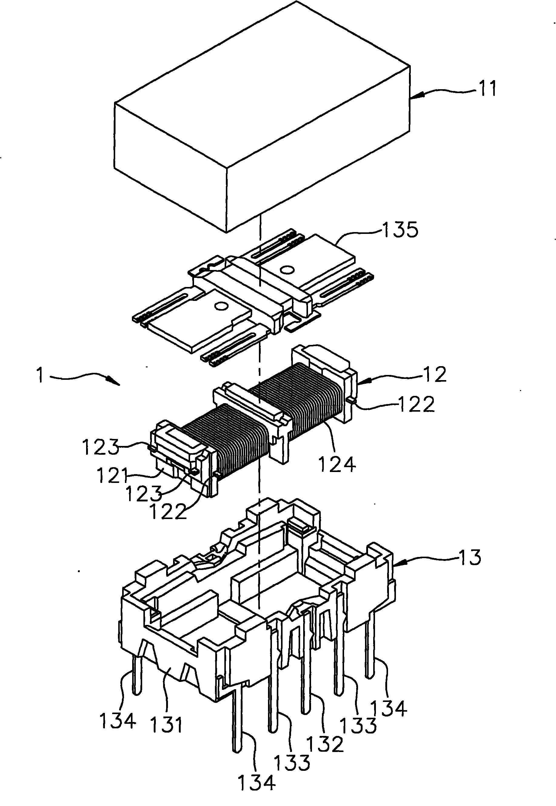
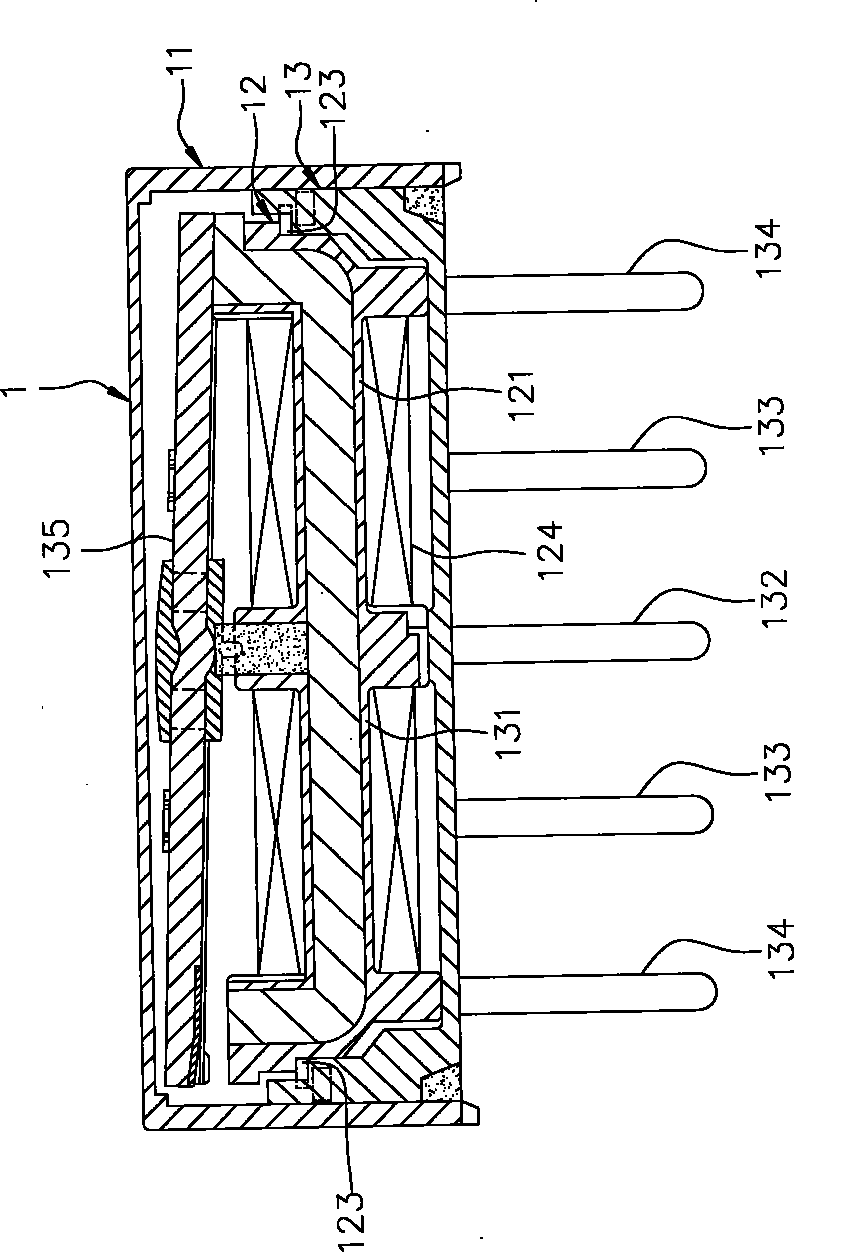
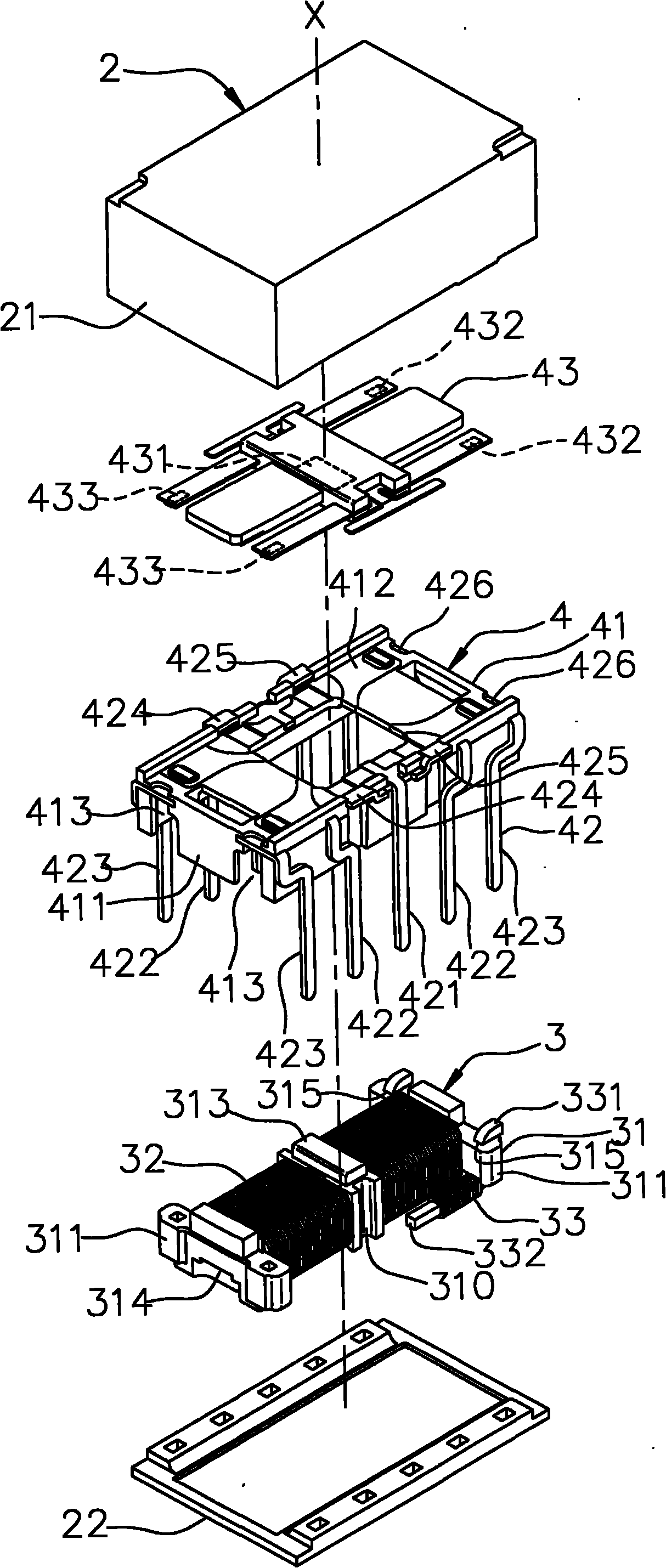
[0021] refer to image 3 and Figure 4 , A preferred embodiment of the electromagnetic relay of the present invention includes a housing 2 , an electromagnetic unit 3 , and a switch unit 4 .

[0022] The case base 2 has a first shell 21 and a second shell 22 that are aligned with each other along an axis X and used to encapsulate the electromagnetic unit 3 and the switch unit 4 .

[0023] The electromagnetic unit 3 has a magnetic wire frame set 31 , a coil set 32 ​​, and a pair of winding terminals 33 . The wire frame set 31 has a wire frame 310 for winding the coil group 32 , a pair of frame rods 311 and the wire frame 310 formed on both ends of the wire frame 310 along a long axis direction and extending along a short axis direction. An integral injection molded core 312, a permanent magnet 313 embedded in the wire frame 310, two grooves 314 formed on the t...


PUM


Abstract

The invention relates to an electromagnetic relay and an assembling method of an electromagnetic unit thereof. The electromagnetic relay comprises a shell block, an electromagnetic unit and a switch unit, wherein the electromagnetic unit is provided with a magnetic coil holder set, at least one coil assembly and at least one pair of wire wrap end pins. The assembling method comprises the following steps of: firstly, penetrating the wire wrap end pins through the coil holder set and arranging in parallel along the direction of a minor axis of the coil holder set; then winding the coil assembly to the coil holder set by taking one of the two wire wrap end pins as the starting end of the coil assembly, and bending the wire wrap end pins along the direction of a long axis by taking the other wire wrap end pin as a terminating end of the coil assembly; and finally, clamping the switch unit and the electromagnetic unit into a whole and encapsulating in the shell block. Thereby, the volume of the electromagnetic unit is reduced by the concealed wire wrap end pins, and the goal of automated assembling work is achieved by an assembling mode of bending and clamping.

Description

technical field [0001] The invention relates to an electromagnetic relay, in particular to an electromagnetic relay which utilizes electromagnetic action to transmit control signals and an assembly method of the electromagnetic unit thereof. Background technique [0002] refer to figure 1 , figure 2 , taking the electromagnetic relay 1 of US Patent No. 4881053 as an example, it mainly includes a shell base 11 , and an electromagnetic unit 12 and a switch unit 13 packaged in the shell base 11 . The electromagnetic unit 12 has a wire frame 121, two pairs of wire winding pins 122 passing through two opposite sides of the wire frame 121, passing through the other two opposite sides of the wire frame 121 and connecting with the pair of wire winding pins 122 respectively. Two pairs of conductive pins 123, and a coil group 124 wound on the bobbin frame 121 with one of the winding pins 122 as the starting end and the other winding pin 122 as the ending end. The switch unit 13 ha...

Claims


Application Information

Patent Timeline
IPC IPC(8): H01H51/22H01H49/00
Inventor 郭明昌
Owner GOOD SKY ELECTRIC
Why Eureka
Try Eureka