Cavity radio frequency device and fly bar thereof for capacitive cross coupling

A technology of cross-coupling and radio-frequency devices, which is applied in the field of capacitive cross-coupling fly rods, can solve the problems of unstable overall structure, reduced power capacity, insufficient coupling amount, etc., to improve space utilization, reduce weight, and increase coupling area effect

Active Publication Date: 2010-08-11
COMBA TELECOM TECH (GUANGZHOU) CO LTD +1
View PDF4 Cites 11 Cited by
  • Summary
  • Abstract
  • Description
  • Claims
  • Application Information

AI Technical Summary

Problems solved by technology

Since the end of the guide strip type flying rod 4 must be formed with two right-angled bending parts 41, 42, and the guide strip itself is relatively thin, its overall structure is very unstable, and it is difficult to ensure its bending during processing or assembly. The bent parts 41, 42 fully meet the requirement of being at right angles. If this requirement cannot be guaranteed, the two bent parts 41, 42 will inevitably be remote or close to the resonant columns 1 and 3.
Insufficient coupling when remote and more coupling when remote, both of which will result in poor consistency
Moreover, once the distance is too close, the power capacity will be greatly reduced, resulting in sparking

Method used


Image

  • Cavity radio frequency device and fly bar thereof for capacitive cross coupling
  • Cavity radio frequency device and fly bar thereof for capacitive cross coupling
  • Cavity radio frequency device and fly bar thereof for capacitive cross coupling

Examples


Embodiment Construction

[0023] Below in conjunction with accompanying drawing and embodiment the present invention will be further described:

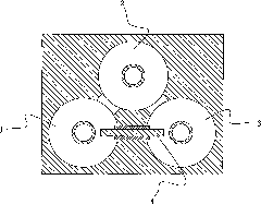
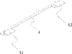
[0024] see Figure 4 , in the schematic diagram of the internal structure of the cavity radio frequency device of the present invention, a metal cavity 1 is presented for the top view angle after the cover (not shown) is removed, and a cavity 10 is provided inside, and the relevant cover has been provided for this Known by those of ordinary skill in the art, it is not shown for the sake of simplicity of expression. In this cavity 10, the known comb line distribution scheme is used along the Figure 4 As shown, a plurality of resonant columns 11, 12, 13 are arranged laterally, a resonant cavity 110, 120, 130 is formed around each resonant column 11, 12, 13, and a flying rod 4 for capacitive cross-coupling is installed On the bottom side wall of the cavity 1, pass through the corresponding through holes 410, 420, 430 of the multi-layer dielectric plates 41, 4...


PUM


Abstract

The invention discloses a cavity radio frequency device and a fly rod thereof for capacitive cross coupling. The cavity radio frequency device adopts a pectinate line resonant cavity arrangement structure. The fly rod is used for realizing the capacitive cross coupling between two non-adjacent resonant cavities of the cavity radio frequency device. The two sides of the fly rod are provided with a coupling piece respectively; the two coupling pieces are connected through strip-lines; the coupling pieces and the strip-lines are all printed onto medium plates; the strip-lines are arranged in a disconnecting way to form an independent middle section and two side sections directly electrically connected with the coupling pieces on the two sides respectively to form a coupling surface; the middle section and the coupling surface are printed onto different medium plates respectively; and the two ends of the middle section are electrically connected with the two side sections respectively. In such a way, the fly rod can endow the cavity radio frequency device with relatively better capacitive cross coupling effect and simultaneously ensures high-power signals smoothly pass through.

Description

【Technical field】 [0001] The invention relates to a cavity radio frequency device, in particular to a fly rod used for capacitive cross-coupling, which is suitable for specific application fields such as filters, combiners and duplexers. 【technical background】 [0002] Cavity RF devices such as filters, combiners, and duplexers play an important role in communication systems. At present, system operators have higher and higher requirements for out-of-band suppression, power capacity and cost of cavity RF devices. [0003] In the path of cavity radio frequency devices, in order to meet the requirements for out-of-band suppression, it is generally realized by adding flying rods for capacitive cross-coupling between resonant cavities. [0004] The traditional method of flying rods for capacitive cross-coupling is realized by adding an ungrounded metal flying rod supported by a dielectric between two separated resonators, such as figure 1 As shown, resonant cavity 1 and resona...

Claims


Application Information

Patent Timeline
Patent Type & Authority Applications(China)
IPC IPC(8): H01P5/00H01P5/04
Inventor 郭春波徐华邸英杰
Owner COMBA TELECOM TECH (GUANGZHOU) CO LTD
Why Eureka
Try Eureka