Multi-user beam shaping method and device based on frequency division duplex system

A beamforming method and frequency division duplexing technology, applied in diversity/multi-antenna systems, transmission systems, radio transmission systems, etc., can solve problems such as lack of technical guidance

Inactive Publication Date: 2010-08-11
ZTE CORP
View PDF5 Cites 24 Cited by
  • Summary
  • Abstract
  • Description
  • Claims
  • Application Information

AI Technical Summary

Problems solved by technology

However, how to deal with the beamforming problem between multiple users is still under study
Especially how to apply it to the FDD system, there is no relevant technical guidance

Method used


Image

  • Multi-user beam shaping method and device based on frequency division duplex system
  • Multi-user beam shaping method and device based on frequency division duplex system
  • Multi-user beam shaping method and device based on frequency division duplex system

Examples


Embodiment Construction
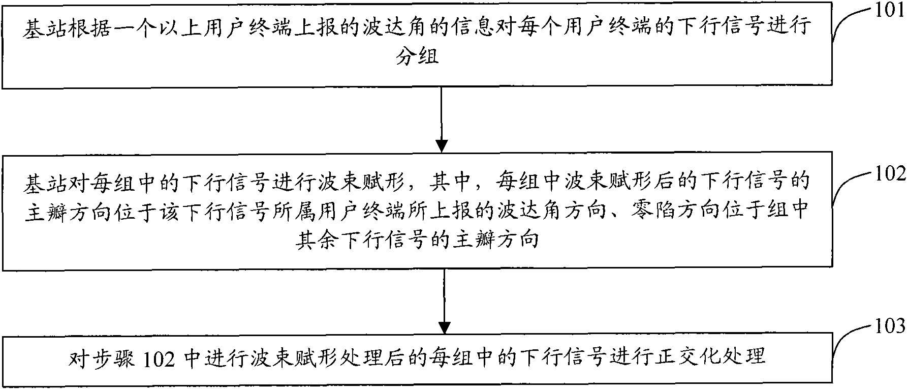
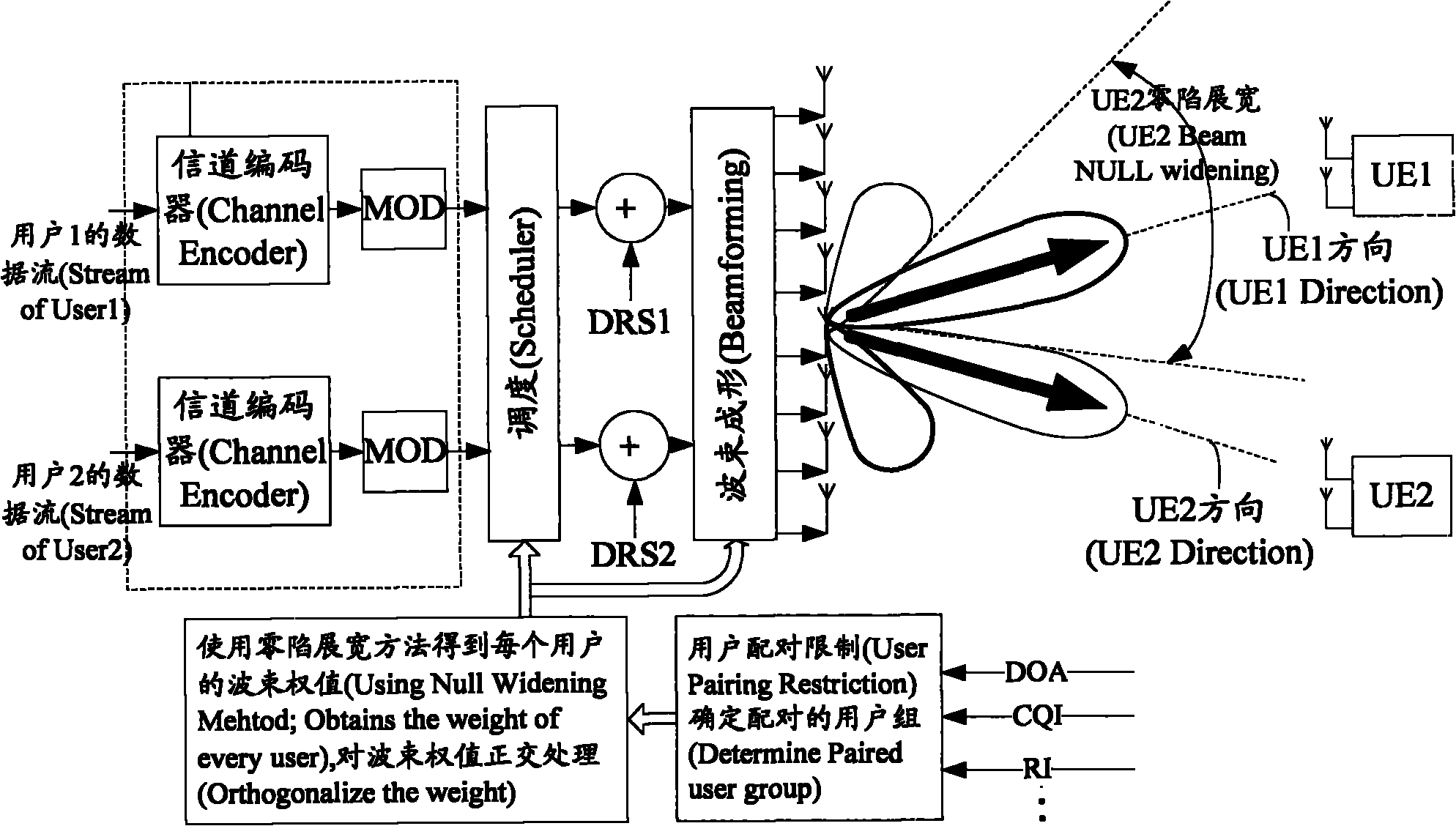
[0037] The basic idea of ​​the present invention is: group the downlink signals according to the angle of arrival (DOA) information reported by the user terminal, the principle of grouping is to make the difference of the angle of arrival between the downlink signals of different user terminals greater than the set angle, so , when performing beamforming on the downlink signal, the shaped beam can be designed according to the angle of arrival of the user terminal, so that the main lobe direction of the downlink signal after beamforming is located at the corresponding wave arrival angle of the user terminal to which the downlink signal belongs. The angular direction, the null direction, is located in the main lobe direction of the remaining downlink signals in the group. According to the purpose of beamforming described above, a corresponding beamforming weight is designed, and the product of the downlink signal to be beamformed is sufficient. The present invention also perform...


PUM


Abstract

The invention discloses a multi-user beam shaping method based on a frequency division duplex system. A base station groups for downlink signals of each user terminal based on information of arrival angles reported by more than one user terminal and carries out beam shaping on the downlink signals in each group, wherein the main lobe direction of downlink signals subjected to beam shaping in each group is arranged in the arrival angle direction reported by a user terminal located by the downlink signals, and the null steering direction is arranged in the main lobe direction of the other downlink signals. The invention also discloses a device for realizing the method. The invention ensures that interference between downlink signals of every two user terminals in each group is further lowered and the downlink signals in the same group can use resources of simultaneous frequency, thereby enhancing the volume of the frequency division duplex system while ensuring the quality of communication.

Description

technical field [0001] The present invention relates to a multi-user beamforming (beamforming) method and device based on a Frequency Division Duplex (FDD, Frequency Division Duplex) system. Background technique [0002] A Multiple Input and Multiple Output (MIMO, Multiple Input and Multiple Output) system has become a technology that has attracted much attention in a Long Term Evolution (LTE, Long Term Evolution) system due to improved channel capacity. In the multi-user MIMO mode, the direction of the shaped beam is designed by designing the weight vector of the appropriate transmitting antenna and receiving antenna, so as to distinguish the signals of multiple users and remove the interference between users. [0003] The beamforming method distinguishes users according to their location, so that multiple users can reuse the same time and frequency resources. For the case of small antenna spacing (0.5λ), it is more beneficial to control the pointing of the beam. Beamform...

Claims


Application Information

Patent Timeline
Patent Type & Authority Applications(China)
IPC IPC(8): H04B7/06H04W16/28H04W24/10
CPCH04W16/28H04B7/086H04B7/0452H04B7/0617
Inventor 郭阳
Owner ZTE CORP
Why Eureka
Try Eureka