Earth leakage detection circuit

A leakage detection and circuit technology, applied in circuit devices, emergency protection circuit devices, measuring electricity, etc., can solve the problems of current flow failure, noise generation, detection failure, etc., and achieve the effect of suppressing misoperation and smooth discharge

Inactive Publication Date: 2010-08-11
DAIKIN IND LTD
View PDF1 Cites 11 Cited by
  • Summary
  • Abstract
  • Description
  • Claims
  • Application Information

AI Technical Summary

Problems solved by technology

[0005] However, in the technology disclosed in the above-mentioned Patent Document 1, as long as the current exceeding the threshold on the positive side and the current below the threshold on the negative side cannot be detected multiple times together, it cannot be detected as a leakage, so there is a problem that it cannot be quickly responded to. question
In addition, for example, when alternating current is converted to direct current by a rectifier such as a semiconductor switching element (thyristor), there is a problem that current leakage in the positive direction cannot be detected even if the current in the positive direction exceeds the positive side threshold value because the current in the negative direction cannot flow. (refer to Figure 9 : Figure explaining the subject of the present invention)
[0006] In addition, when using an integrated circuit with a leakage detection function, since noise may be generated by the operation of the integrated circuit, there is a problem that countermeasures against noise must also be devised in addition to the leakage detection function.

Method used


Image

  • Earth leakage detection circuit
  • Earth leakage detection circuit
  • Earth leakage detection circuit

Examples


no. 1 approach

[0029] (1.1 Outline structure)

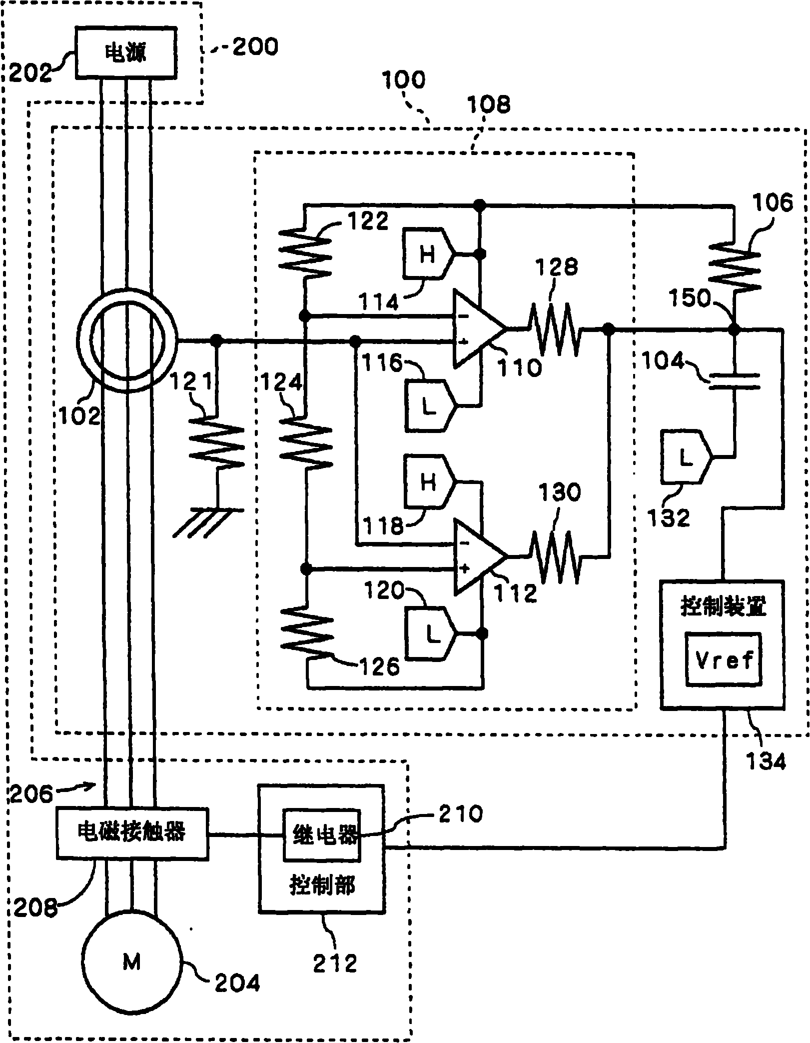
[0030] figure 1 It is a diagram showing the leakage detection circuit 100 according to the first embodiment of the present invention. Leakage detection circuit 100 is provided, for example, in air conditioner 200. This air conditioner 200 includes: power supply 202, motor (electric load) 204, circuit 206 that supplies power supply current to motor 204, and an electromagnetic contactor that switches conduction / non-conduction of circuit 206. 208, and a control unit 212 having a relay 210 for operating the electromagnetic contactor 208.

[0031] (1.2 Circuit structure)

[0032] Leakage detection circuit 100 has: a zero-phase converter 102 and a capacitor 104 that detect ground current in circuit 206 and output a zero-phase current, and a capacitor 104 that detects a ground current and outputs a zero-phase current when the zero-phase current exceeds a predetermined positive-side threshold or is lower than a predetermined negative-side threshold....

no. 2 approach

[0061] In the above-mentioned embodiment, the mode in which only the capacitor 104 is provided at the output terminal of the circuit 108 has been described, but the present invention is not limited thereto. Here, as a second embodiment of the present invention, an embodiment in which a capacitor 104 and a filter circuit are provided at the output end of the circuit 108 will be described with reference to the drawings. In addition, unless otherwise specified, elements having the same functions as those in the above-mentioned embodiment are given the same reference numerals, and descriptions thereof are omitted.

[0062] (2.1 Outline structure)

[0063] Figure 6 It is a figure which shows the leakage detection circuit 100A of 2nd Embodiment of this invention. Leakage detection circuit 100A is provided in air conditioner 200 in the same manner as in the above-described embodiment.

[0064] (2.2 Circuit structure)

[0065] The electric leakage detection circuit 100A has a fil...


PUM


Abstract

The invention provides an earth leakage detection circuit. A zero-phase current transformer (102) detects a ground fault current and outputs a zero-phase current. When the voltage of the zero-phase current exceeds a positive side threshold (TH1) or drops below a negative side threshold (TH2), an open collector output circuit (108) operates to discharge a capacitor (104). When the inter-plate voltage of the capacitor (104) drops below a threshold voltage (Vref), a control means (134) detects the fact as earth leakage and notifies the control section (212) of an air conditioner (200) to this effect.

Description

technical field [0001] The invention relates to the leakage detection function. Background technique [0002] According to the prior art, a leakage detection function has been proposed to detect the presence or absence of leakage by multiple detections of currents exceeding a predetermined positive threshold and currents below a predetermined negative threshold. For example, it is disclosed in Patent Document 1. . [0003] Patent Document 1: (Japanese) Unexamined Patent Publication No. 2003-219552 [0004] The purpose, characteristics, aspects and advantages of the present invention will be clarified by the following detailed description and accompanying drawings. [0005] However, in the technology disclosed in the above-mentioned Patent Document 1, as long as the current exceeding the threshold on the positive side and the current below the threshold on the negative side cannot be detected multiple times together, it cannot be detected as a leakage, so there is a problem...

Claims


Application Information

Patent Timeline
Patent Type & Authority Applications(China)
IPC IPC(8): H02H3/347G01R31/02H02H3/16H02P23/00
CPCH02H3/347G01R31/025G01R31/52
Inventor 堂前浩键村纪雄增田透
Owner DAIKIN IND LTD
Why Eureka
Try Eureka