Long range low frequency resonator and materials

A frequency and transmitter technology, applied in transmission systems, loop antennas, radio transmission systems, etc., can solve problems such as insufficient power delivery and low efficiency

Inactive Publication Date: 2010-08-11
QUALCOMM INC
View PDF6 Cites 20 Cited by
  • Summary
  • Abstract
  • Description
  • Claims
  • Application Information

AI Technical Summary

Problems solved by technology

Difficulty with previous attempts is low efficiency

Method used


Image

  • Long range low frequency resonator and materials
  • Long range low frequency resonator and materials
  • Long range low frequency resonator and materials

Examples


Embodiment Construction

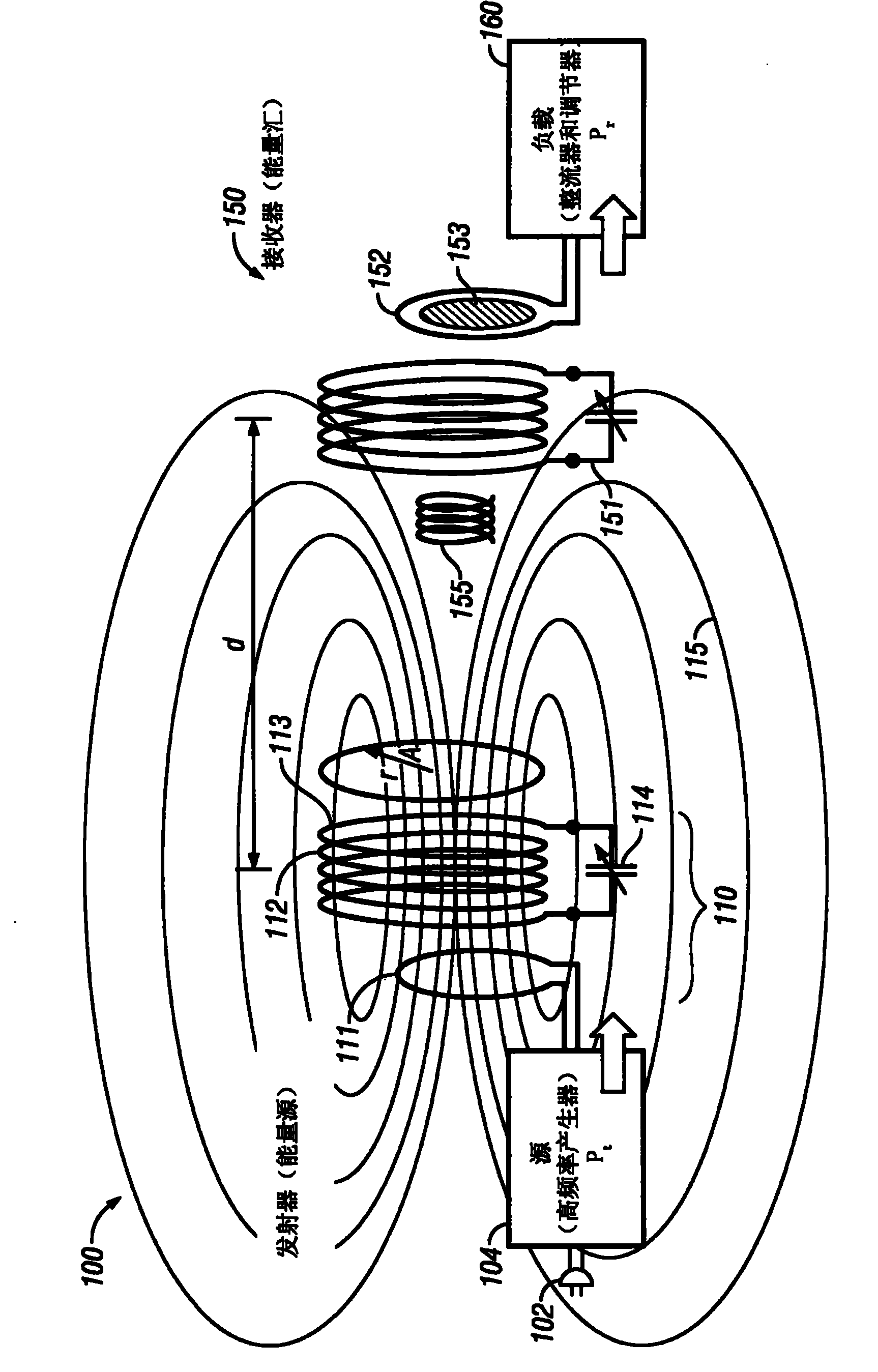
[0010] figure 1 A basic example is shown in . The power transmitter assembly 100 receives power from a source (eg, AC plug 102). The frequency generator 104 is used to couple energy to the antenna 110 (here, a resonant antenna). Antenna 110 includes an inductive loop 111 that is inductively coupled to a high-Q resonant antenna portion 112 . The resonant antenna comprises N number of coil loops 113, each loop having a radius R A . A capacitor 114 (shown here as a variable capacitor) is connected in series with the coil 113, forming a resonant tank. In the described embodiment, the capacitor is a completely separate structure from the coil, but in some embodiments the self-capacitance of the wires forming the coil may form capacitance 114 .

[0011] Frequency generator 104 may preferably be tuned to antenna 110, and also selected for FCC compliance.

[0012] This embodiment uses a multi-directional antenna. 115 shows the energy output in all directions. Antenna 100 is no...


PUM


Abstract

Transmission of power at low frequencies, e.g. less than 1 MHz The power can be transmitted in various ways, using different structures included stranded wire such as Litz wire. The inductor can also use cores of ferrites for example. Passive repeaters can also be used.

Description

[0001] This application claims priority to Provisional Application No. 60 / 955,598, filed August 13, 2007, which is incorporated herein by reference in its entirety. Background technique [0002] It is desirable to transfer electrical energy from a source to a destination without using wires to direct the electromagnetic field. Difficulties with previous attempts have been low efficiency coupled with insufficient amounts of delivered power. [0003] Wireless power transfer is described in our prior and provisional applications including, but not limited to, Serial No. 12, filed January 22, 2008, entitled "Wireless Apparatus and Methods." / 018,069, the entire disclosure of which is incorporated herein by reference. [0004] The system may use transmit and receive antennas, which are preferably resonant antennas that generally resonate within, for example, 10% resonance, 15% resonance or 20% resonance. The antenna is preferably of small size to allow it to fit into a mobile han...

Claims


Application Information

Patent Timeline
IPC IPC(8): H04B7/005H04B7/00
CPCH01Q7/00H04B5/0037H02J5/005H01Q1/2225H02J50/50H02J50/12
Inventor 汉斯彼得·威德默卢卡斯·西贝尔奈杰尔·P·库克
Owner QUALCOMM INC
Why Eureka
Try Eureka