
Rubber bushing compacting mould

A rubber bushing and die technology, applied in metal extrusion dies, metal extrusion, manufacturing tools, etc., can solve problems such as chemical bond damage, rubber layer cracking, rubber bushing damage and failure, etc.

Inactive Publication Date: 2010-08-18
AVIC HUIYANG AVIATION PROPELLER
View PDF6 Cites 5 Cited by
  • Summary
  • Abstract
  • Description
  • Claims
  • Application Information

AI Technical Summary

Problems solved by technology

[0003] During the use of the rubber bushing, the operation of the variable pitch rod drives the outer metal bushing to do variable pitch movement. One side of the rubber layer in the middle of the inner and outer metal bushes is subjected to tensile stress, and the other side is subjected to compressive stress. Under the action of stress, the rubber layer is easy to separate from the inner and outer metal bushings from the joint, and the instantaneous overload will cause the tensile stress on the side of the rubber layer to be greater than the tensile limit of the rubber, which will damage the chemical bonds between the rubber molecules and form microscopic cracks , after repeated use, the crack spreads, causing the rubber layer to break, and eventually leads to the damage and failure of the rubber bushing
In order to avoid the above situation, it is necessary to use a mold to squeeze the outer metal bushing, so that the rubber layer between the inner and outer metal bushes produces a certain pre-squeeze deformation, so as to increase the distance between the inner and outer metal bushes and the rubber layer. The purpose of the adhesive force, so as to prolong the service life of the product, but the current industrial mold can not meet the processing requirements of this extrusion process

Method used


Image

  • Rubber bushing compacting mould
  • Rubber bushing compacting mould
  • Rubber bushing compacting mould

Examples


Embodiment

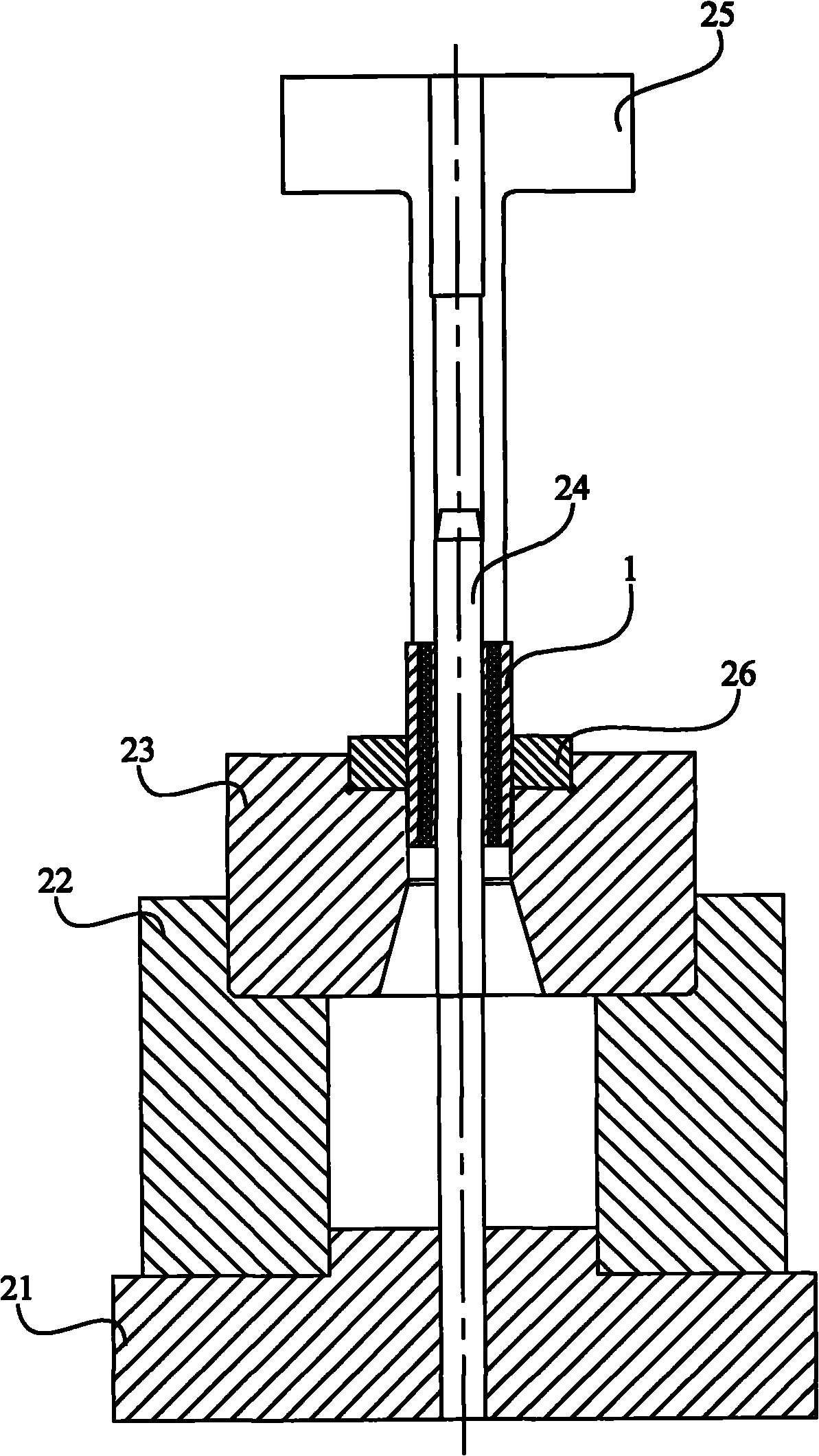
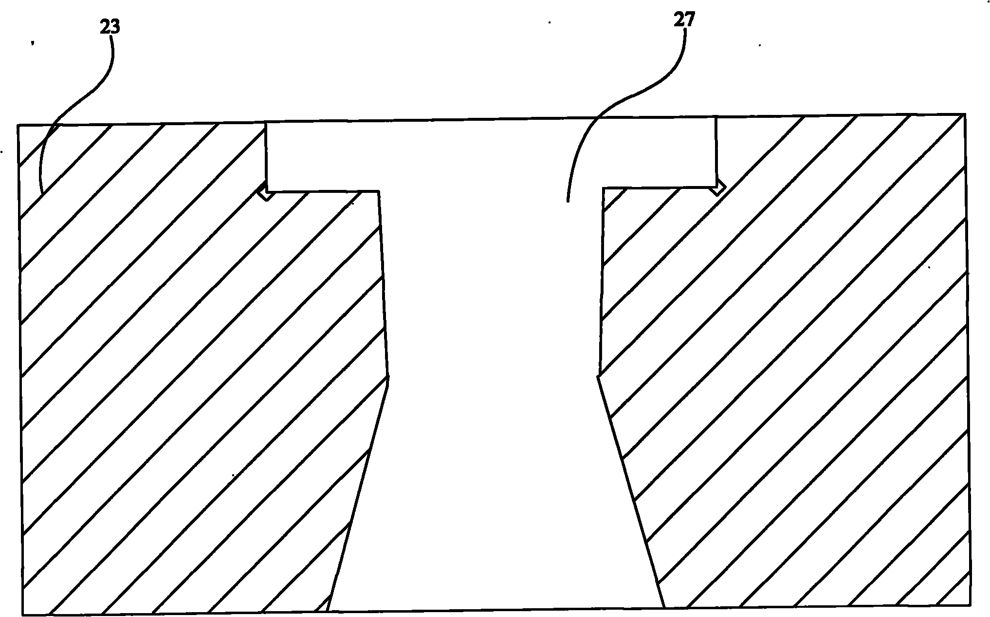
[0013] figure 2 It is the structural representation of the embodiment of the rubber bush extrusion die of the present invention, as figure 2 As shown, it includes a base 21, a support ring 22, an extrusion block 23, a guide post 24 and an indenter 25. During the extrusion process, the electronic tension machine is loaded on the upper end surface of the indenter 25, and the rubber bushing 1 is pressed downward. displacement compression. The guide post 24 is fixedly installed on the base 21. Under the positioning and guiding action of the guide post 24, the central axis of the rubber bush 1 will not deviate from the axis of the squeezed part of the rubber bush extrusion die during the extrusion process, avoiding the occurrence of If the amount of shrinkage is uneven or the coaxiality is seriously out of tolerance, the shape and position tolerance of the rubber bushing during the entire shrinkage process is guaranteed. The squeeze block 23 is provided with a through hole 27, ...


PUM


Abstract

The invention discloses a rubber bushing compacting mould. The mould comprises a pressure head, a base, a support ring, a compacting block and a guide pillar, wherein the guide pillar is fixed on the base, the compacting block is provided with a through-hole, the upper part of the through-hole is tapered, the upper part of the taper of the through-hole is a 3-degree tapered bore, and the lower part of the through-hole is flared. The invention also comprises a baffle ring which is arranged on the compacting block. Therefore, by using the rubber bushing compacting mould of the invention, the external metal bushing can be compacted, the adhesive force between the internal and external metal bushings and the rubber layer can be increased, the rubber layer of the rubber bushing can be prevented from dropping and the service life of the rubber bushing can be prolonged.

Description

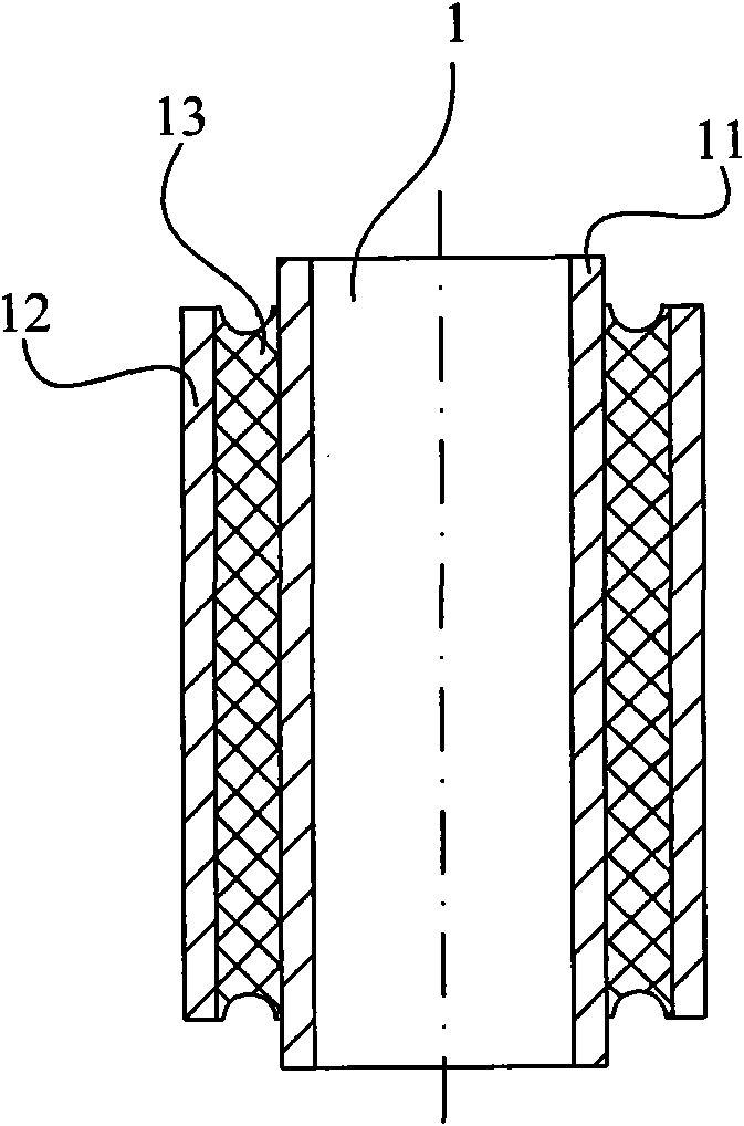
technical field [0001] The invention relates to a mold, in particular to a rubber bush extrusion mold. Background technique [0002] The rubber bushing is the rubber elastic joint of the tail rotor pitch rod of the helicopter, which has the characteristics of simple structure and good shock absorption and sound insulation performance. The rubber bushing 1 is vulcanized by the inner metal bushing 11, the outer metal bushing 12 and the rubber layer 13 sandwiched between them. figure 1 It is the structure diagram of the rubber bushing. [0003] During the use of the rubber bushing, the operation of the variable pitch rod drives the outer metal bushing to do variable pitch movement. One side of the rubber layer in the middle of the inner and outer metal bushes is subjected to tensile stress, and the other side is subjected to compressive stress. Under the action of stress, the rubber layer is easy to separate from the inner and outer metal bushings from the joint, and the inst...

Claims


Application Information

Patent Timeline
IPC IPC(8): B21C25/08B21C26/00
Inventor 李志忠王航空何灿文刘培元高晓波边若鹏
Owner AVIC HUIYANG AVIATION PROPELLER
Learn More