Wear measuring method based on profile duplication of grooving and milling cutter

A tool wear and measurement method technology, which is applied in the direction of measuring/indicating equipment, manufacturing tools, metal processing machinery parts, etc., can solve the problems that affect the surface quality and dimensional accuracy of the workpiece processing, affect the efficiency of the machine tool, damage the machine tool, etc., and achieve contour replication The effect of flexible measurement methods, simple measurement methods, and simple settings

Inactive Publication Date: 2010-08-18
NANJING UNIV OF AERONAUTICS & ASTRONAUTICS
View PDF1 Cites 25 Cited by
  • Summary
  • Abstract
  • Description
  • Claims
  • Application Information

AI Technical Summary

Problems solved by technology

There are two aspects to the treatment of tool wear. On the one hand, if the tool wear is lower than the blunt standard, it will cause waste because the actual life of the tool is not fully utilized and increase manufacturing costs; on the other hand, if the tool wear If the tool is blunt or damaged, it will affect the surface quality and dimensional accuracy of the workpiece, and even damage the machine tool in severe cases
The key to solving these problems lies in the automatic and real-time detection of the tool wear state. Therefore, it is necessary to measure, model and control the tool wear in the CNC machining process. By measuring the tool wear, the tool wear model is established, and then the

Method used


Image

  • Wear measuring method based on profile duplication of grooving and milling cutter
  • Wear measuring method based on profile duplication of grooving and milling cutter
  • Wear measuring method based on profile duplication of grooving and milling cutter

Examples


Embodiment Construction

[0021] The specific implementation steps of the wear measurement method proposed by the present invention based on the tool wear profile replication of slot cutting and milling will be further described below.

[0022] (1) Experimental program design

[0023] According to the type of tool material and workpiece material, considering the number of tool edges, spindle speed, feed rate, cutting depth and cutting width parameters in machining, the experimental program of tool wear CNC milling was designed by orthogonal experiment method.

[0024] (2) Copy material preparation

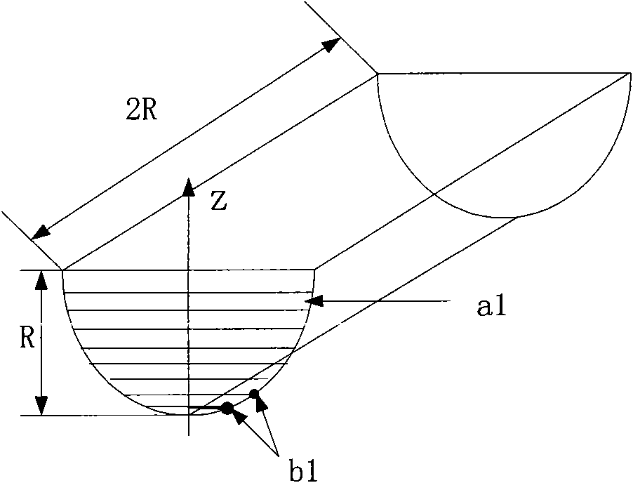
[0025] According to the tool wear shape to be copied in the NC machining experiment plan and the number of machining experiments, prepare one or several pieces of finely processed copy material blocks. The above copy materials are easy-to-process materials with negligible tool wear, and the shape is a cuboid. CNC machining In the experimental plan, add 20mm to the maximum value of the tool radius as the th...


PUM


Abstract

The invention relates to a cutter wear measuring method based on the grooving and milling profile duplication, belonging to the cutter wear measuring field. The method is characterized by comprising the following steps of: installing a workpiece material to be processed and a duplicate material on the same numerically-controlled machine workbench; firstly duplicating the initial profile of a cutter on the duplicate material before experiment, that is, feeding the cutter on the duplicate material in a grooving and milling mode for a preset distance, wherein the duplicate material is a tractable material of which the wear on the cutter can be ignored; processing the workpiece material according to the experimental scheme, and duplicating the profile of the worn cutter on the duplicate material after each processing is completed; processing the cutter wear geometric element shape on the duplicate material, extracting characteristic values, designing a measurement scheme based on the measurement requirements of the characteristic values, and measuring on three coordinates measuring machines after all experimental schemes are finished. The invention can obtain the cutter wear amount without closing down the tool, and has the advantages of simple setting for the cutter wear measurement, less measurement data, simple processing and batch processing and measurement.

Description

Technical field [0001] The invention relates to the problem of tool wear measurement in numerical control machining, in particular to a measurement method based on groove cutting and milling wear contour replication which can obtain tool wear in the numerical control machining process without stopping the machine tool in the numerical control machining. It is used in the field of tool wear measurement for CNC milling. Background technique [0002] In CNC milling, as the direct executor of the cutting process, the tool inevitably suffers from wear and damage during the cutting process of the workpiece. The change of the tool state directly leads to an increase in cutting force, an increase in cutting temperature, and damage to the surface of the workpiece. Increased roughness, out-of-tolerance workpiece dimensions, changes in chip color, and generation of cutting chatter. There are two aspects to the treatment of tool wear. On the one hand, if the tool wear is lower than the...

Claims


Application Information

Patent Timeline
IPC IPC(8): B23Q17/09
Inventor 张臣周来水王小平刘西卉郭松
Owner NANJING UNIV OF AERONAUTICS & ASTRONAUTICS
Why Eureka
Try Eureka