Concrete pump truck

A concrete pump truck and car body technology, which is applied in the direction of concrete transportation, etc., can solve the problems that hinder the expansion of the model of the movable concrete pump, the size of the width direction cannot be changed, the cost of licensing fees, insurance fees, etc., so as to expand the applicability of the product and improve Mobility, weight reduction effect

Inactive Publication Date: 2010-08-18
安良平
View PDF3 Cites 6 Cited by
  • Summary
  • Abstract
  • Description
  • Claims
  • Application Information

AI Technical Summary

Problems solved by technology

[0005] 1) Because the concrete concrete cylinder and the main oil cylinder are placed obliquely, under the action of gravity, the concrete needs to be sucked upwards, which affects the efficiency of sucking concrete;
[0006] 2) Because the existing vehicle-mounted pump uses a ready-made car chassis instead of a special-purpose chassis, some unnecessary additional costs are added, such as: the registration fee, insurance premium and car scrapping period that must be spent with the car chassis;
[0007] 3) The girder of the concrete pump is repeated with the girder of the automobile chassis, which not only increases the weight but also increases the cost; the length direction dimension of the automobile chassis girder is variable, but the width direction dimension cannot be changed (the distance between the girders of the automobile chassis is 860-870MM, which is Unified), this limitation makes the chassis of the small-sized movable concrete pump relatively high in cost compared to the whole machine, and the ultra-large movable concrete pump cannot be realized, which seriously hinders the expansion of the model of the movable concrete pump

Method used


Image

  • Concrete pump truck
  • Concrete pump truck
  • Concrete pump truck

Examples


Embodiment 1

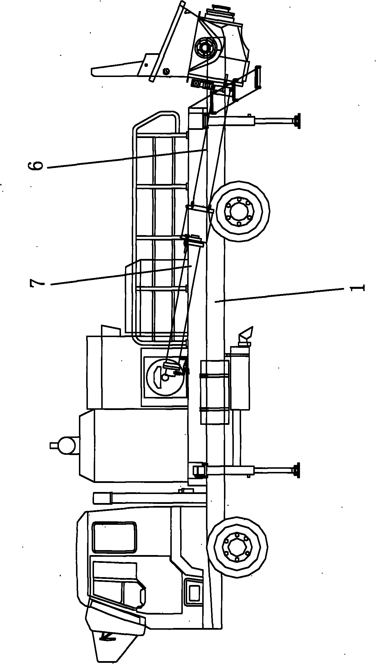
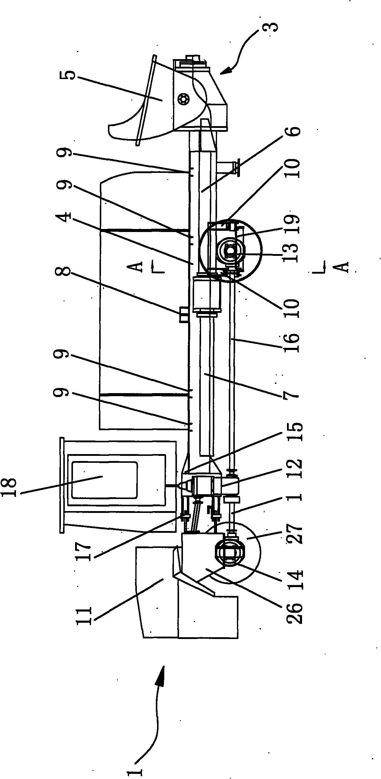
[0033] Such as figure 2 , 4 The shown concrete pump truck includes a car body 1, a frame 2 horizontally arranged on the car body 1, a pumping mechanism 3 installed on the frame 2, a power mechanism and a steering mechanism. The frame 2 includes two horizontally arranged U-shaped beams 4 , and the openings of the two U-shaped beams 4 are arranged opposite to each other, and a beam assembly straddling between the two U-shaped beams 4 . The pumping mechanism 3 generally includes: a hopper 5 , a concrete cylinder 6 connected to the hopper 5 , and a main oil cylinder 7 connected to the concrete cylinder 6 .

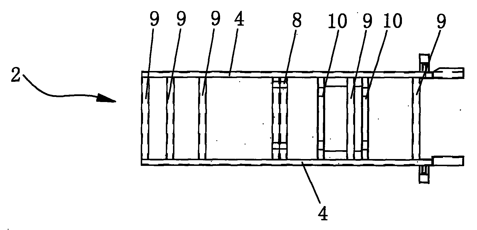
[0034] Such as image 3 As shown, the crossbeam assembly includes a first crossbeam 8, a second crossbeam 9 and a third crossbeam 10, wherein: the centerline of the first crossbeam 8 is located above the horizontal plane where the U-shaped beam 4 is located, and the centerline of the second crossbeam 9 is located at the U-shaped On the horizontal plane where the girder 4 i...

Embodiment 2

[0039] Such as Figure 5As shown, the difference from Embodiment 1 is that a gearbox 12 is directly installed on the front end of the U-shaped girder 4, the input end of the gearbox 12 is connected with the walking engine 11 through a belt 20, and the output end of the gearbox 12 is driven by a universal joint. The shaft 16 is connected to the drive rear axle 13 . The front steering bridge 14 is installed under the second beam 9, and the piston rod of the steering oil cylinder is connected with the front steering wheel 27 to drive the rotation of the unpowered front steering wheel 27.

Embodiment 3

[0041] Such as Figure 6 , 7 As shown, the difference from Embodiment 1 is that the two third beams 10 lower than the U-shaped beam 4 are also fixed supports for driving the rear axle 13. The third beam 10 is equipped with a leaf spring hinge seat 21, and the leaf spring is hinged. Seat 21 is equipped with shock-absorbing leaf spring 22, and driving rear axle 13 is elastically connected on the shock-absorbing leaf spring 22 by a U-shaped bolt, and driving rear axle 13 adapts to uneven road surface by the elasticity of shock-absorbing leaf spring 22.


PUM


Abstract

The invention relates to a concrete pump truck which comprises a main body, a frame, a pumping mechanism, a power mechanism and a steering mechanism, wherein the frame comprises two U-shaped girders which are arranged horizontally; the openings of the two U-shaped girders are opposite to each other and across a crossbeam assembly between the two U-shaped girders; the crossbeam assembly comprises a first crossbeam, a second crossbeam and a third crossbeam; and the center lines of the first crossbeam, the second crossbeam and the third crossbeam are respectively positioned above, on and below the horizontal planes on which the U-shaped crossbeams are located; and the pumping mechanism is horizontally installed in the space erected between the first crossbeam and the third crossbeam. The pumping mechanism of the invention is horizontally arranged, so the pumping mechanism can intake the concrete with higher efficiency, thereby improving the performance of the concrete pump; the U-shaped girders and the running system of the concrete pump truck share common girders, thereby reducing the weight and the cost; and the restriction to the inner space of the girders is reduced, thereby deriving more autotype concrete pump models.

Description

technical field [0001] The invention relates to a concrete pump truck without an automobile chassis. Background technique [0002] At present, when developing high-rise buildings in a community, usually several buildings are constructed at the same time on one construction site. Therefore, in order to save equipment investment, it is hoped that one concrete pump can solve the concrete delivery problem of all high-rise buildings on the site. The existing vehicle-mounted concrete pump The pump came into being, and it pumps concrete for each building by moving between tall buildings. [0003] The vehicle-mounted concrete pump is realized by directly erecting the pumping mechanism and the hydraulic system driving the concrete pump on the chassis of the vehicle. Such as figure 1 Shown: Because the layout of the girders of the car chassis, the drive shaft and the rear axle are basically fixed, the girders of the car chassis are usually buckled by two U-shaped girders, and multip...

Claims


Application Information

Patent Timeline
Patent Type & Authority Applications(China)
IPC IPC(8): B60P3/16
Inventor 安良平
Owner 安良平
Why Eureka
Try Eureka