Strip material applicator of case sealer

A technology of applicator and fixed unit, applied in the field of material applicator, can solve the problem of time-consuming and achieve the effect of replacement

Active Publication Date: 2010-08-18
LAMUS ENTERPRISES
View PDF10 Cites 23 Cited by
  • Summary
  • Abstract
  • Description
  • Claims
  • Application Information

AI Technical Summary

Problems solved by technology

Obviously, replacing a spent roll of tape with a new one is a time consuming operation as it involves passing the leading end of the tape from the new roll through the tape applicator

Method used


Image

  • Strip material applicator of case sealer
  • Strip material applicator of case sealer
  • Strip material applicator of case sealer

Examples


Embodiment Construction

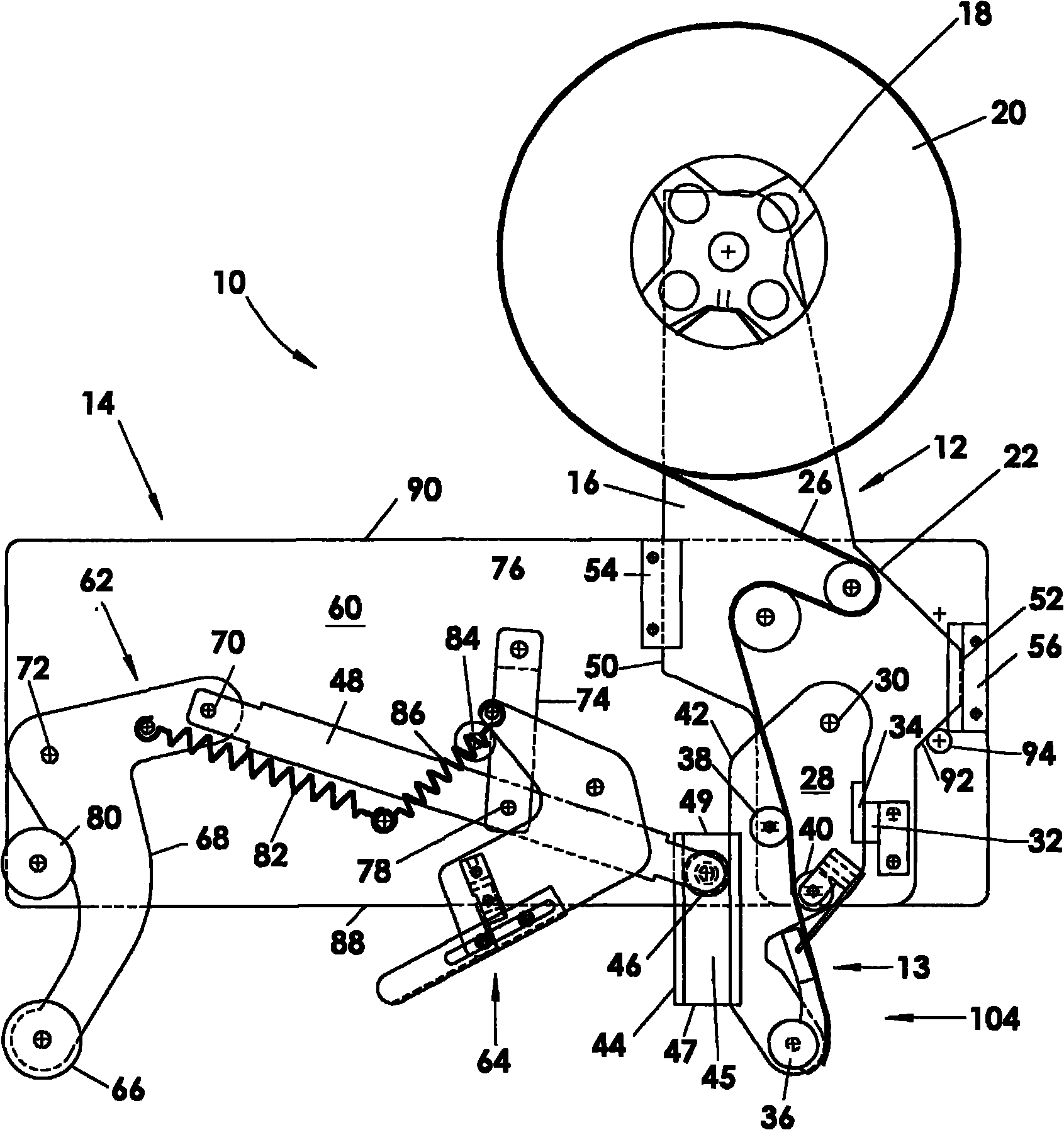
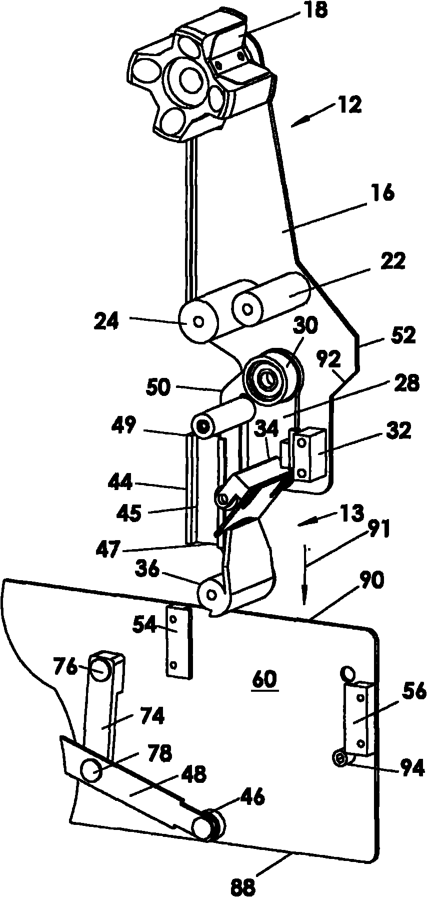
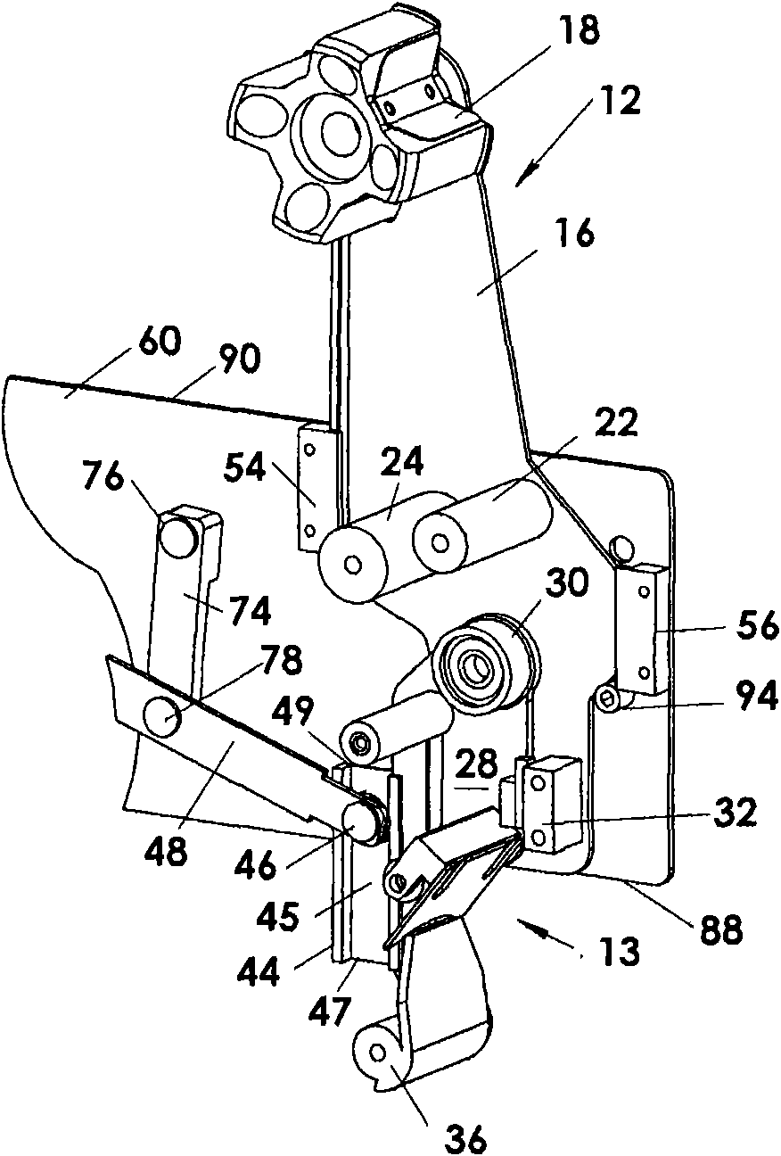
[0025] As shown in the drawings, the tape applicator 10 of the present invention consists of two parts, a detachable unit 12 that is removably mounted in a fixed unit 14, and a removable unit 12 that is fixed to use the tape applicator (see Figures 1 to 5 , Figures 1 to 3 Show Top Tape Applicator, Figure 4 with 5 The fixing unit 14 on the machine (not shown) of the bottom tape applicator is shown.

[0026] The removable unit 12 is formed by an auxiliary frame 16 on which is mounted the front part 13 of the tape applicator mechanism. The front portion 13 ("front" because it is used to apply the tape to the front end 102 of the case 100 as the tape moves past the tape applicator 10) includes a belt for mounting the tape. A tape reel stand 18 for a roll 20 and, if desired, tape guide rollers 22 and 24 around which the tape 26 passes. A front link 28 is pivotally mounted to the subframe 16 on an axle 30 and forms part of the front section 13 . Front link 28 is releasably h...


PUM


Abstract

The invention relates to a strip material applicator of a case sealer. The strip material applicator or a strip supplying head is formed by the combination of two separated devices, that is to say, the strip material applicator or the strip supplying head comprises a detachable unit and a fixing unit, wherein the detachable unit is positioned at the front part of the strip material applicator; the fixing unit is positioned at the rear part of the strip material applicator; and the detachable unit is jointed with the fixing unit through a padlock positioned between the detachable unit and the fixing unit so as to obtain the interactive action of the traditional strip material applicator, that is to say, the strip material applicator separates the traditional strip material applicator into two separated parts so as to obtain the capability of fast replacing strip materials 26 and reduce safety risks.

Description

technical field [0001] The present invention relates to an improved tape applicator for a case sealing device, and more particularly to a tape applicator that facilitates changing tape rolls to improve the efficiency of the device. Background technique [0002] Conventional tape applicators or tape supply heads for applying adhesive tape to boxes or cartons etc. to seal the lid of the box closed typically include a front link with a leading end of the tape applied to the a wiping roller in front of the carton that moves relatively head-on; a trailing arm with a wiping roller for wiping the tape on the adjacent surface of the case and along the tail end of the case, and a cutting knife located at The two arms are between and are actuated to cut the strip to length and have a free end adjacent to a wiper roller on the front linkage in position to be applied to the next case. These applicators are common in the industry and work well. See for example US Patent 5,676,298 issue...

Claims


Application Information

Patent Timeline
Patent Type & Authority Applications(China)
IPC IPC(8): B65H35/07B65B51/06
Inventor 林诚德
Owner LAMUS ENTERPRISES
Why Eureka
Try Eureka