
Yarn winding machine and yarn winding method

A winding machine and yarn technology, which is applied in the direction of thin material processing, conveying filamentous materials, transportation and packaging, etc., and can solve the problems of package yarn skipping, unwinding, poor winding and tightening force, etc.

Active Publication Date: 2010-08-18
TMT MACHINERY INC
View PDF1 Cites 9 Cited by
  • Summary
  • Abstract
  • Description
  • Claims
  • Application Information

AI Technical Summary

Problems solved by technology

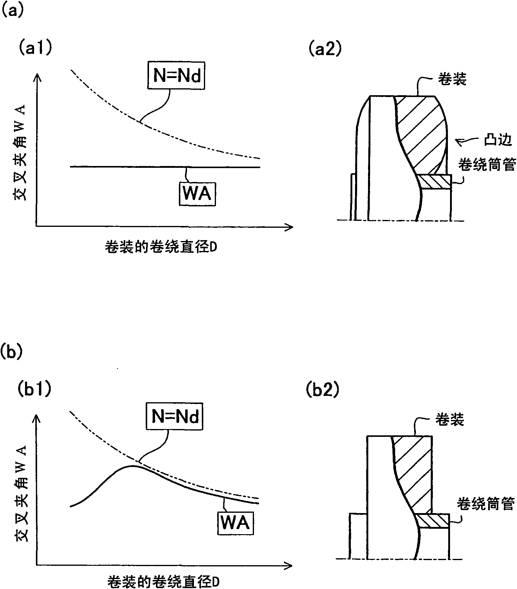
[0012] However, in the winding of yarns such as elastic yarns, since the winding tightening force is large, it is more difficult to figure 1 The convex edge shown in (a2) of (a) is more pronounced
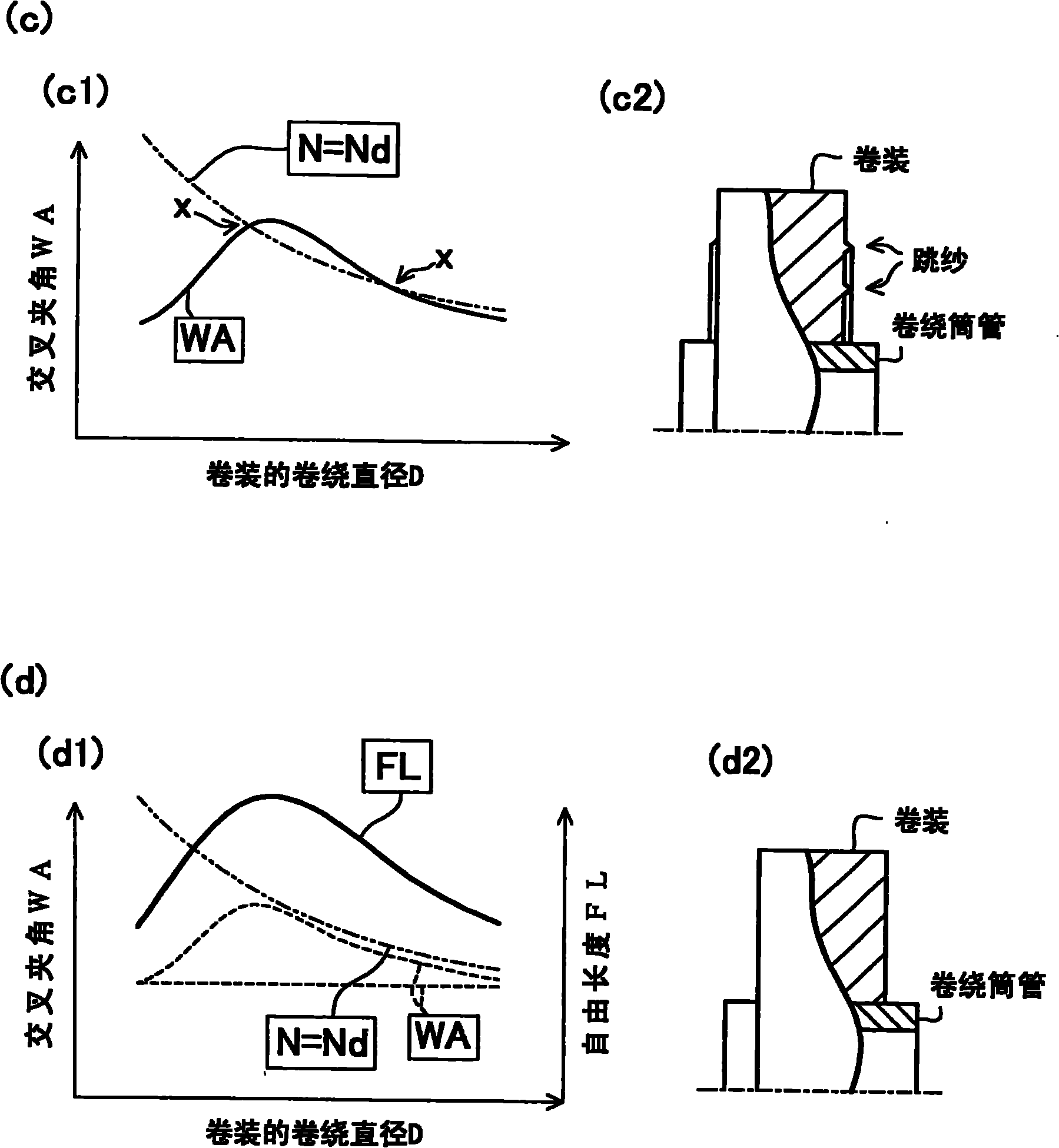
And, if such a conspicuous convex edge also wants to be suppressed by the technology of the above-mentioned patent document 1, then as figure 2 As shown in (c1) in (c), the intersecting angle WA must be further increased anyway. As a result, the line of the intersecting angle WA crosses the two-dot chain line indicating the generation condition of the winding overlap, and the above-mentioned winding overlap occurs. When it is the winding diameter D corresponding to the intersection point indicated by the symbol X in the figure, such as figure 2 As shown in (c2) in (c), there are problems such as yarn skipping at the end surface of the package or the above-mentioned unwinding failure.
In this way, in the technique of the above-mentioned Patent Document 1, even if the bulge can be suppressed, depending on the type of yarn, it may be difficult to avoid the occurrence of overlapped windings.

Method used


Image

  • Yarn winding machine and yarn winding method
  • Yarn winding machine and yarn winding method
  • Yarn winding machine and yarn winding method

Examples


Embodiment Construction

[0042] Hereinafter, a winder 1 as a yarn winding machine according to the first embodiment of the present invention will be described based on the drawings. Image 6 This is a front view of the winder according to the first embodiment of the present invention. Figure 7 System diagram for the winder.

[0043] The winder 1 winds an elastic yarn 2 as a yarn onto a bobbin 3 to form a package 4 (refer to Picture 10 ) Of the yarn winding machine. In addition, although the yarn winding machine that winds the elastic yarn 2 will be described below, the invention of the present application is not limited to this, and may be a yarn winding machine that winds yarns of other yarn types. Such as Image 6 As shown, the winder 1 has a body frame 5, a turntable 6, a sliding box 16, a traverse device 7, a contact roller 8, and a free length changing unit 9. Such as Figure 7 As shown, each structure of the winder 1 is electrically connected to the control unit 80 (control device). The control ...


PUM


Abstract

The present invention provides a technique to prevent possible ribbon winding regardless of yarn type while inhibiting possible bulging. The winder 1 includes a contact roller 8 configured to come into contact with a package 4 during formation of the package 4, a traverse device 7 located upstream side of the contact roller 8 in the traveling direction of an elastic yarn 2, a free length varying means 9 for enabling the free length FL of the elastic yarn 2 located between the contact roller 8 and the traverse device 7 to be varied during formation of the package 4, and a control section 80 configured to control the free length varying means 9 in such a manner that the free length FL is increased during winding start of the package 4 and then reduced toward winding end.

Description

Technical field [0001] The invention relates to a yarn winding machine and a yarn winding method. Background technique [0002] As a technique for preventing so-called bulging when the yarn traversed by the traverse device is wound onto the winding bobbin by a touch roller to form a package, Patent Document 1 describes that the yarn is used in the initial stage of winding. A technology to increase the cross angle (winding angle) and relax the tension of the yarn layer at this initial stage. Moreover, in this Patent Document 1, it is also described that in order to achieve the purpose of avoiding winding overlap, the crossing angle is gradually reduced until the winding ends, so as to prevent the winding number from being less than one. [0003] [Patent Document 1] Japanese Patent Application Publication No. 9-71367 [0004] However, if the technique of Patent Document 1 mentioned above is adopted, there is no problem in the case where a relatively small degree of bulging occurs, an...

Claims


Application Information

Patent Timeline
Patent Type & Authority Applications(China)
IPC IPC(8): B65H54/28
CPCB65H2701/319B65H54/381B65H49/18B65H54/38B65H59/00
Inventor 堀哲也桥本欣三
Owner TMT MACHINERY INC
Learn More