Sterile negative pressure isolation facility of capping machine

A negative pressure isolation and capping machine technology, applied in the field of isolation facilities, can solve the problems of pollution between capping, dust pollution, rubber plug loosening, etc., achieve cleanliness standards, and eliminate dust pollution.

Inactive Publication Date: 2011-10-05
ZHEJIANG VACIN BIO PHARMA LTD
View PDF0 Cites 0 Cited by
  • Summary
  • Abstract
  • Description
  • Claims
  • Application Information

AI Technical Summary

Problems solved by technology

The "minimum requirement" for the capping of non-terminal sterilized products in the 1998 version is 100,000-level (level D); most manufacturers put the capping machine under the 100-level laminar flow hood in the 100,000-level capping room. A large amount of aluminum shavings, glass shavings and other dust generated during capping pollute the capping room quite seriously, making it difficult for the dynamic monitoring of the cleanliness of the capping room to meet the standard
After the drug is filled and corked and before capping, the state of the rubber stopper at the mouth of the bottle is actually a "not completely sealed state", and there are cases where the rubber stopper is loose or even skipped, and the dust pollution between the capping and capping will endanger the sterility of the drug state, and this single-bottle contamination is difficult to detect
When my country's drug regulatory department revised the 2010 version of GMP, it clearly stipulated that the crimping of non-terminal sterilized products must be carried out in an environment of "level A under the background of level B"; The pollution of chips to the capping room cannot meet the requirements of the new version of GMP
Therefore, the prior art has the problems and deficiencies of dust pollution and the cleanliness of the capping environment being difficult to meet standards

Method used


Image

  • Sterile negative pressure isolation facility of capping machine
  • Sterile negative pressure isolation facility of capping machine
  • Sterile negative pressure isolation facility of capping machine

Examples


Embodiment Construction

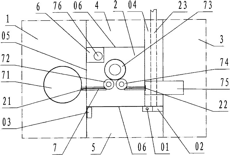
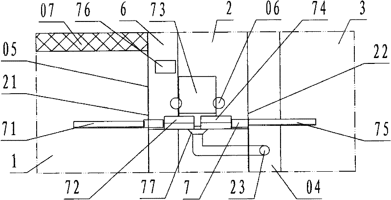
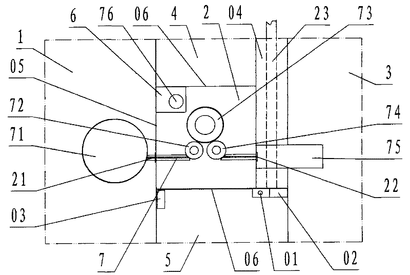
[0022] refer to Figure 1 ~ Figure 2 , a sterile negative pressure isolation facility for a capping machine of the present invention, comprising a filling room 1, a capping cabin 2, a bottle outlet room 3, a operating cabin 4, a second operating cabin 5, a transfer cabin 6, and a capping machine 7, wherein: the filling room 1, the capping cabin 2, the bottle outlet room 3, the A operation cabin 4, the B operation cabin 5, and the transfer cabin 6 are each work workshop and cabin enclosed by a transparent partition wall 05 ; According to the description of the left and right front and rear directions, the capping cabin 2 is the cabin of the capping operation; the left side wall of the capping cabin is the filling room 1 of the filling operation provided with filling equipment, and the left side partition wall of the capping cabin is provided with There is a bottle inlet 21 communicating with the filling room 1, and the bottle inlet is provided with a valve; the right next door ...


PUM


Abstract

The invention discloses a sterile negative pressure isolation facility of a capping machine, which comprises a filling room (1), a capping cabin (2), a bottle discharge room (3), an A operation cabin (4), a B operation cabin (5), a transmission cabin (6) and the capping machine (7). The facility separates all functional parts and manual operation areas of the capping machine with transparent partition walls, to form mutually isolated working areas and functional cabin facilities; a negative pressure exhaust facility is arranged below the capping machine, for removing the dust produced in capping in real time; all the areas and the cabins are isolated and communicated by sterile air pressure difference, i.e. the technical scheme of sterile negative pressure isolation, communication and operation overcomes the problems and the defects of dust pollution and difficulty of the cleanliness of the capping environment in meeting standards; and the provided sterile negative pressure isolation facility of the capping machine ensures that the capping environment of the capping machine achieves the purposes that the dust pollution is eliminated and the cleanliness meets the standards through sterile negative pressure isolation.

Description

technical field [0001] The invention relates to an isolation facility for aseptic operation of pharmaceutical production equipment, specifically refers to an aseptic negative pressure isolation of a capping machine that uses an aseptic negative pressure isolation method to make the capping machine operate in a sterile environment. facility. Background technique [0002] The capping machine is a device used to seal the corked containers with aluminum caps or aluminum-plastic caps in a clean environment in the production of pharmaceuticals or food. After the medicine is filled and stoppered or freeze-dried and pressed, it needs to be transported to the capping machine for capping and sealing. The "minimum requirement" for the capping of non-terminal sterilized products in the 1998 version is 100,000-level (level D); most manufacturers put the capping machine under the 100-level laminar flow hood in the 100,000-level capping room. A large amount of aluminum shavings, glass sh...

Claims


Application Information

Patent Timeline
Patent Type & Authority Patents(China)
IPC IPC(8): B67C7/00
Inventor 范丹斗游坚波
Owner ZHEJIANG VACIN BIO PHARMA LTD
Why Eureka
Try Eureka