Roller Dust Collector

A technology of dust collector and roller, which is applied in the direction of chemical instruments and methods, separation of dispersed particles, filtration of dispersed particles, etc., can solve the problems of increasing equipment running resistance, potential safety hazards of dust collectors, etc., to reduce the possibility of dust explosion and facilitate Manufacturing, dust explosion reduction effect

Inactive Publication Date: 2017-09-22
江苏百斯特环境工程有限公司
View PDF6 Cites 0 Cited by
  • Summary
  • Abstract
  • Description
  • Claims
  • Application Information

AI Technical Summary

Problems solved by technology

[0002] Dust collector is a kind of equipment that separates dust from flue gas. Common dust collectors are divided into bag filter, pulse dust collector, cyclone dust collector and explosion-proof dust collector, etc.; Inflammable and explosive gas or water vapor or fine dust is enough to cause explosion or fire and other dangerous places; common explosion-proof dust collectors prevent explosions by controlling the concentration of dust; under the action of the main fan of the system, dusty gas flows from the dust collector The air inlet enters the air box of the dust collector for pretreatment of the dust-containing gas, and then enters the dust removal chambers of the upper box from the bottom; the dust is adsorbed on the outer surface of the filter cartridge, and the filtered clean air passes through the filter cartridge and enters the upper chamber. The clean air chamber of the box is collected to the air outlet for discharge; as the filtering condition continues, the dust accumulated on the outer surface of the filter cartridge will accumulate more and more, which will increase the running resistance of the equipment accordingly. Therefore, the traditional explosion-proof dust removal The dust collector needs to be cleaned in time and regularly. Excessive accumulation of dust will make the dust collector have a greater safety hazard

Method used


Image

  • Roller Dust Collector
  • Roller Dust Collector
  • Roller Dust Collector

Examples


Embodiment

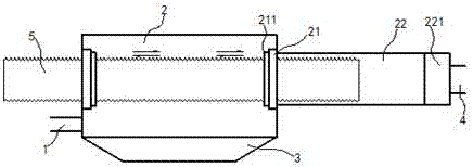
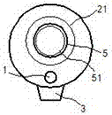
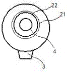
[0015] exist Figure 1 to Figure 3 In the shown embodiment, the roller dust collector includes an air intake pipe 1, a dust removal chamber 2, an ash hopper 3 and an exhaust pipe 4; the cylindrical dust removal chamber 2 is placed horizontally on the body; the ash hopper 3 is installed in the lower part of the dust removal chamber 2, and the air inlet pipe 1 is placed on the left side wall of the dust removal chamber 2; drive rings 21 are symmetrically installed on the left and right side walls of the dust removal chamber 2, so that The drive ring 21 is driven to rotate by the drive motor; the inner ring surface of the drive ring 21 is engraved with threaded grooves; a cleaning brush 211 is installed on the side ring edge of the drive ring 21; The dust removal roller 5, in the present embodiment, the length of the dust removal roller 5 is at least twice the length of the dust removal chamber 2; the two ends of the dust removal roller 5 extend out of the dust removal chamber 2 ...


PUM


Abstract

The invention relates to a rotary roller dust collector. The rotary roller dust collector includes an air inlet pipe, a dust removal chamber, an ash hopper and an exhaust pipe; the cylindrical dust removal chamber is placed horizontally on the machine body; The drive rings are symmetrically installed on the left and right side walls; the inner ring surface of the drive ring is engraved with thread grooves; a hollow dust removal roller is installed in the dust removal chamber, and the two ends of the dust removal roller After penetrating through the drive ring, it extends out of the dust removal cavity; the outer peripheral wall of the dust removal roller is engraved with thread lines matching the thread groove; the position of the blocking plate in the inner cavity of the dust removal roller matches the position of the left side wall; A purification cover is also fixedly installed on the right side wall of the dust removal chamber, and the exhaust pipe is installed at the end of the purification cover; one end of the dust removal roller extends into the purification cover; The device can realize real-time dust removal and dust removal operations, effectively prevent local accumulation of dust, and improve the safety of dust removal and purification.

Description

technical field [0001] The invention relates to a dust collector, in particular to an explosion-proof dust collector. Background technique [0002] Dust collector is a kind of equipment that separates dust from flue gas. Common dust collectors are divided into bag filter, pulse dust collector, cyclone dust collector and explosion-proof dust collector, etc.; Inflammable and explosive gas or water vapor or fine dust is enough to cause explosion or fire and other dangerous places; common explosion-proof dust collectors prevent explosions by controlling the concentration of dust; under the action of the main fan of the system, dusty gas flows from the dust collector The air inlet enters the air box of the dust collector for pretreatment of the dust-containing gas, and then enters the dust removal chambers of the upper box from the bottom; the dust is adsorbed on the outer surface of the filter cartridge, and the filtered clean air passes through the filter cartridge and enters t...

Claims


Application Information

Patent Timeline
Patent Type & Authority Patents(China)
IPC IPC(8): B01D50/00B01D46/26
CPCB01D46/26B01D50/20
Inventor 彭扣华
Owner 江苏百斯特环境工程有限公司
Why Eureka
Try Eureka