Supercharge Your Innovation With Domain-Expert AI Agents!

Wind generator system

A wind power generation system, wind power technology, applied in the direction of wind power generation, wind power engine, wind power motor combination, etc., can solve problems such as damage, failure to generate electricity, grid waste, etc.

Inactive Publication Date: 2010-08-18
薛晓户
View PDF0 Cites 2 Cited by
  • Summary
  • Abstract
  • Description
  • Claims
  • Application Information

AI Technical Summary

Problems solved by technology

[0004] 2. Low current quality: The electricity generated by wind power will vary due to the size of the wind, and it is difficult to control it stably at 50Hz (ie 3000 revolutions per minute). It is difficult to generate the same frequency, so it will weaken the current energy in the grid, and even produce other destructive effects
[0005] 3. Low power generation: At present, most of the wind power generation methods are limited to the traditional three-blade wind power generation method, and the driving efficiency is very small. Its disadvantage is that the power is low, and it is difficult to compare with thermal power and hydropower.
[0006] 4. High wind speed requirements: high wind speed requirements, too small wind speed will not generate electricity, too large and easy to damage cannot generate electricity
When the wind energy is strong, the electricity generated by many wind farms will exceed the load of the grid, and when the wind energy is weak, the electricity generated is very little or even zero, which will cause waste to the grid
[0007] 5. Low propulsion efficiency and poor utilization efficiency: when the wind force is very small, it is difficult to generate huge energy
Moreover, due to the different propulsion principles of the design of the wind propulsion device, its work efficiency is different
The conversion of the final accumulated energy must be realized by efficient propulsion devices, but the propulsion efficiency of existing propulsion devices is relatively low, generally only reaching about 30%

Method used


Image

  • Wind generator system
  • Wind generator system
  • Wind generator system

Examples


Embodiment Construction

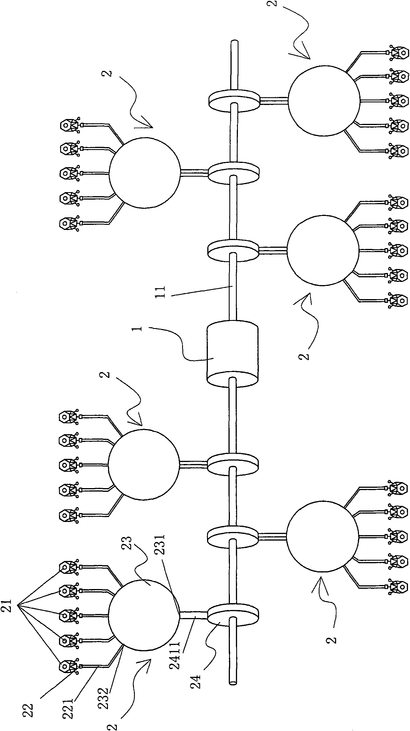
[0062] Such as figure 1 As shown, the present invention provides a wind power generation system, the wind power generation system includes a generator 1 and more than two wind propulsion power units 2, the power output end of each wind propulsion power unit 2 is connected to the generator 1 Each wind propulsion power unit 2 includes more than one wind propulsion device 21 , more than one air compression device 22 , air storage tank 23 and airflow propulsion device 24 . Wherein, each wind propulsion device 21 is driven by the wind to output rotational power; each air compression device 22 is connected to the power output end of a wind propulsion device 21, driven by the power output by the wind propulsion device 21 and output through an airflow Passage 221 outputs airflow; Described air tank 23 has airflow outlet 231 and more than one airflow inlet 232, wherein each airflow inlet 232 is connected to the airflow output passage 221 of an air compression device 22; The airflow in...


PUM


Abstract

The invention provides a wind generator system comprising a motor and more than two wind propelling power units, wherein the power output end of each wind propelling power unit is connected with the power input end of the motor; each wind propelling power unit comprises more than one wind propelling device, more than one air compressor, an air storage tank and an airflow propelling device, wherein each air compressor is connected to the power output end of one wind propelling device, and airflows are driven by power output by the wind propelling devices and output through an airflow output passage; each airflow inlet of the air storage tank is connected with the airflow output passage of one air compressor; and the wind propelling devices output rotation power through the driving of airflows flowing through an airflow inflow passage. The wind generator system enables the electric quantity sent by the motor to be relatively stable and enhances the stability of output voltage and the current quality of the electricity generation of the motor.

Description

technical field [0001] The invention relates to the field of wind energy utilization, in particular to a wind power generation system. Background technique [0002] Wind power is one of the most important ways the world obtains energy. With the gradual reduction or even exhaustion of coal, petrofossil energy and even nuclear fuel, people's energy costs are getting higher and higher. With the increase of carbon dioxide emissions, the corresponding disasters on the earth are also increasing. The depletion of the earth's resources is firstly the depletion of energy resources, especially the depletion of fossil energy. However, wind is a natural product of air flow caused by the sun shining on the earth. Strictly speaking, wind energy is a product of solar energy. As long as the sun shines on the earth for a day, wind energy will exist for a day. Wind energy is safe, clean, abundant and inexhaustible. The most important thing is that wind energy is a permanent and abundant l...

Claims


Application Information

Patent Timeline
Patent Type & Authority Applications(China)
IPC IPC(8): F03D9/00F03D9/02F03D9/17
CPCY02E60/15Y02E10/72Y02E70/30
Inventor 薛晓户
Owner 薛晓户
Features
  • R&D
  • Intellectual Property
  • Life Sciences
  • Materials
  • Tech Scout
  • Unparalleled Data Quality
  • Higher Quality Content
  • 60% Fewer Hallucinations
Learn More