
System for exhaust gas recirculation in a motor vehicle

a technology for recirculation system and exhaust gas, which is applied in the direction of charge feed system, combustion engine, non-fuel substance addition to fuel, etc., can solve the problems of corrosion damage, large exhaust gas mass flow rate, and difficult to obtain using known egr systems, so as to reduce corrosion damage

Inactive Publication Date: 2006-11-09
BEHR GMBH & CO KG
View PDF12 Cites 89 Cited by
  • Summary
  • Abstract
  • Description
  • Claims
  • Application Information

AI Technical Summary

Benefits of technology

[0008] It is one object of the present invention to provide an improved device and system for cooled exhaust gas recirculation, in particular a system that reduces corrosion damage in heat exchangers that are exposed to the exhaust gas.

Problems solved by technology

Since the demands on exhaust gas purification are becoming stricter, greater exhaust gas mass flow rates are required, which are difficult to obtain using known EGR systems.
A disadvantage of known EGR systems is that, during cooling of the recirculated exhaust gas, an acidic condensate is produced that can lead to corrosion damage when flowing through an aluminum heat exchanger, in particular a charge air cooler, that is positioned downstream.
This problem occurs to a greater extent when the EGR mass flow is extracted at the low pressure side of the exhaust gas turbine.

Method used


Image

  • System for exhaust gas recirculation in a motor vehicle
  • System for exhaust gas recirculation in a motor vehicle
  • System for exhaust gas recirculation in a motor vehicle

Examples


Embodiment Construction

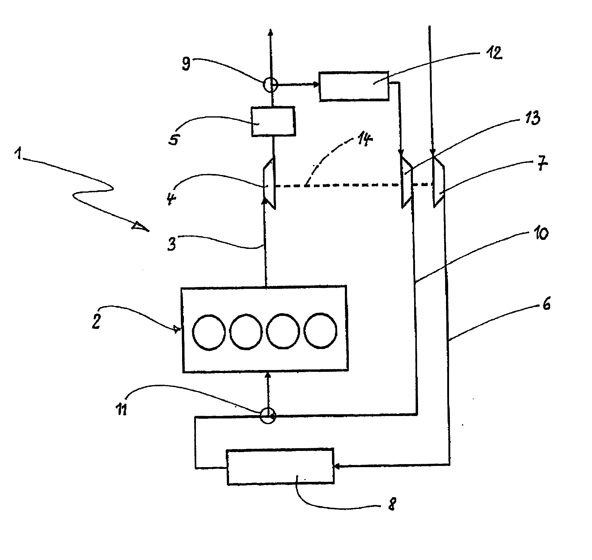
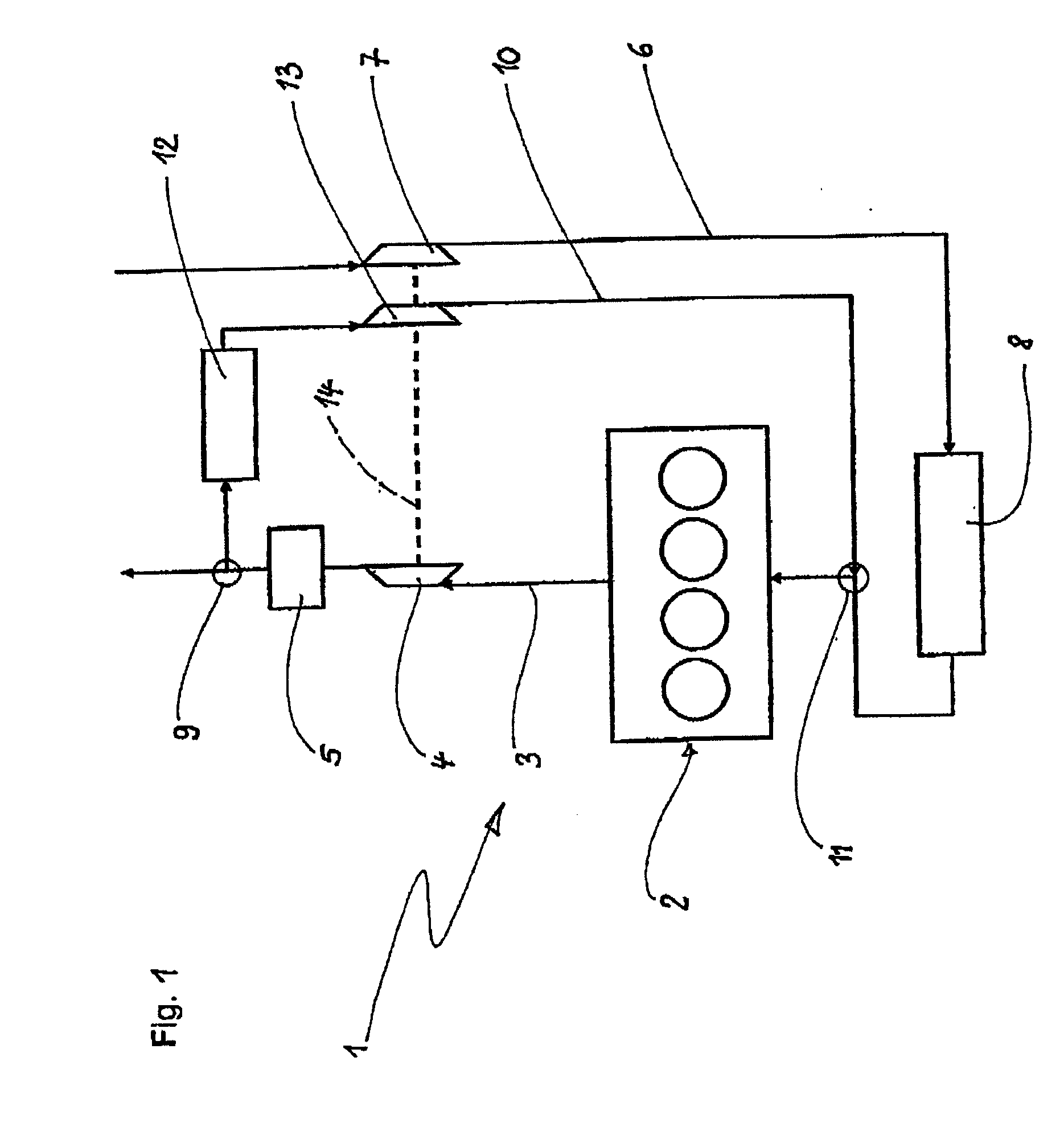
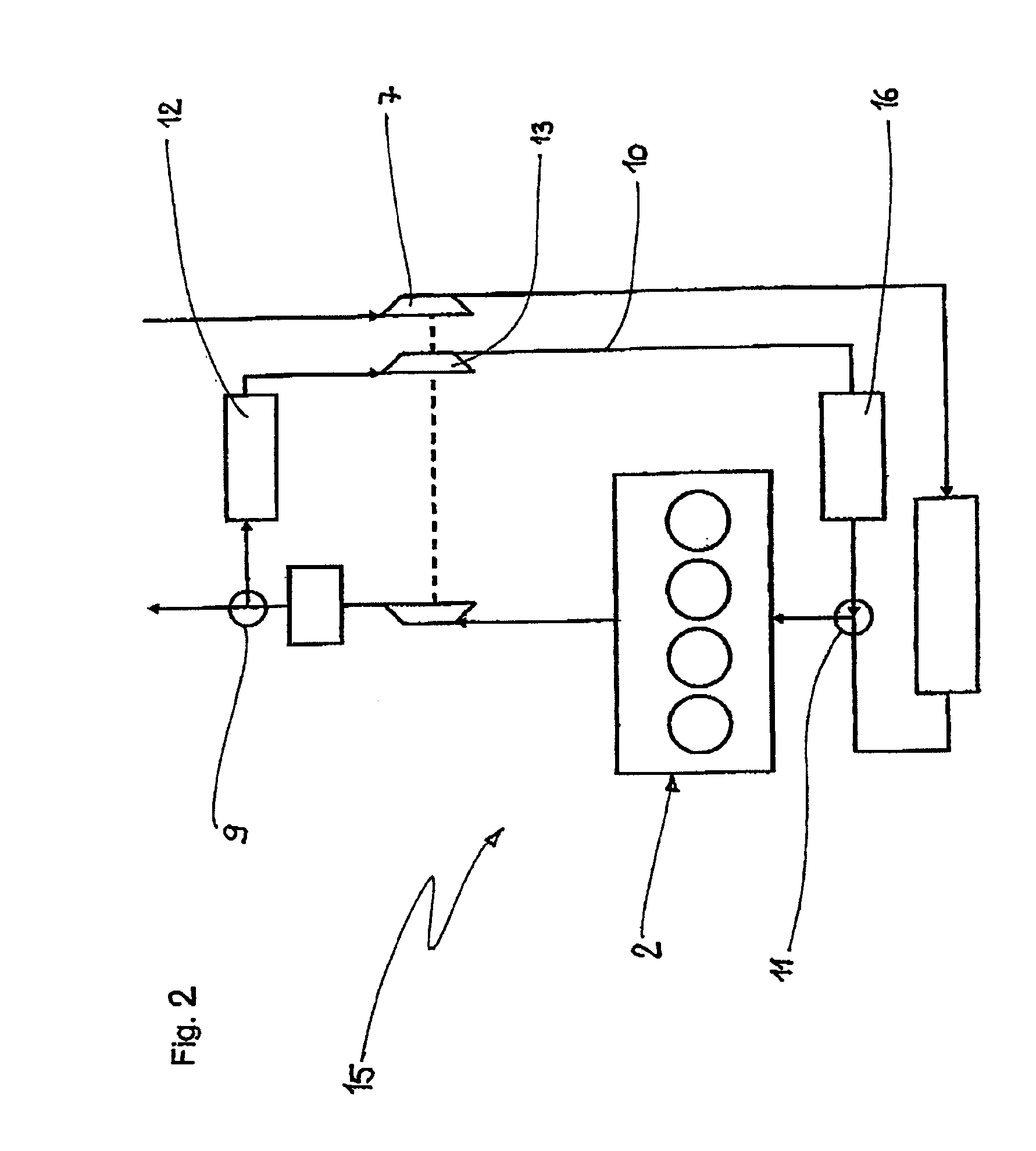
[0016] According to a preferred aspect of the invention, the intake combustion air and the recirculated, cooled exhaust gas are compressed separately. This is preferably achieved by means of two separate compressors, a fresh air or charge air compressor and an exhaust gas compressor, which are preferably arranged on one shaft that is driven by the exhaust gas turbine. This brings about the advantage that the cooled and compressed exhaust gas, which may contain acidic condensate, can be fed directly to the internal combustion engine. The charge air cooler, which is produced from aluminum materials, can therefore be bypassed. The charge air cooler can therefore be exposed only to “clean” fresh air which is compressed by means of the charge air cooler. Corrosion of the aluminum heat exchanger is thus prevented. Another advantage according to the invention is that no separate condensate separator is necessary for the acidic condensate contained in the exhaust gas.

[0017] According to on...


PUM


Abstract

A system for recirculation of cooled exhaust gas from a vehicle internal combustion engine includes an internal combustion engine (2) having an intake system (6) and an exhaust gas system (3), an exhaust gas recirculation (EGR) line (10) that contains an exhaust gas cooler (12), an exhaust gas turbine (4) arranged in the exhaust gas system, (3) and a charge air compressor (7) and a charge air cooler (8) arranged in the intake system (6). The exhaust gas stream is extracted at the low pressure side (9) of the exhaust gas turbine (4). An exhaust gas compressor (13) is arranged in the EGR line (10), and the recirculated exhaust gas stream can be fed to the intake system downstream of the charge air cooler (8).

Description

CROSS-REFERENCE TO RELATED PATENT APPLICATIONS [0001] The right of foreign priority is claimed under 35 U.S.C. § 119(a) based on Federal Republic of Germany Application No. 10 2005 017 905.3, filed Apr. 18, 2005, the entire contents of which, including the specification, drawings, claims and abstract, are incorporated herein by reference. BACKGROUND OF THE INVENTION [0002] The invention relates to a heat exchange device and system for cooling recirculated exhaust gas of an internal combustion engine in a motor vehicle. [0003] Exhaust gas recirculation (for short: EGR), especially cooled exhaust gas recirculation, is used in modern vehicles to satisfy mandated reductions in emissions of particulates and pollutants, in particular nitrogen oxides. Since the demands on exhaust gas purification are becoming stricter, greater exhaust gas mass flow rates are required, which are difficult to obtain using known EGR systems. [0004] Known EGR systems are typically arranged on the high pressure...

Claims


Application Information

Patent Timeline
IPC IPC(8): F02B29/04F02B33/44
CPCF02M25/0711Y02T10/121F02M25/0739F02M26/08F02M26/34
Inventor GESKES, PETER
Owner BEHR GMBH & CO KG
Learn More