Plasma immersion injection structure

A plasma and immersion injection technology, which is applied in the direction of plasma, discharge tube, electrical components, etc., can solve the problems of prolonging the pre-pumping time, corrosion of the inner wall of the chamber, and injection pollution, so as to reduce the introduction of impurity ions, improve efficiency, Reduce the effect of injection contamination

Active Publication Date: 2013-06-19
中科九微科技有限公司
View PDF10 Cites 2 Cited by
  • Summary
  • Abstract
  • Description
  • Claims
  • Application Information

AI Technical Summary

Problems solved by technology

PIII devices also have some disadvantages. For example, PIII devices are mostly single-chamber devices. The atmosphere is directly filled into the injection chamber when placing the pre-treated substrate and taking the processed substrate, which will prolong the pre-pumping time before injection. , will also introduce impurity ions introduced into the air, thereby causing injection pollution, and at the same time, components such as oxygen and water vapor in the air will also act on the inner wall of the chamber, resulting in corrosion and damage to the inner wall of the chamber

Method used


Image

  • Plasma immersion injection structure
  • Plasma immersion injection structure

Examples


Embodiment 1

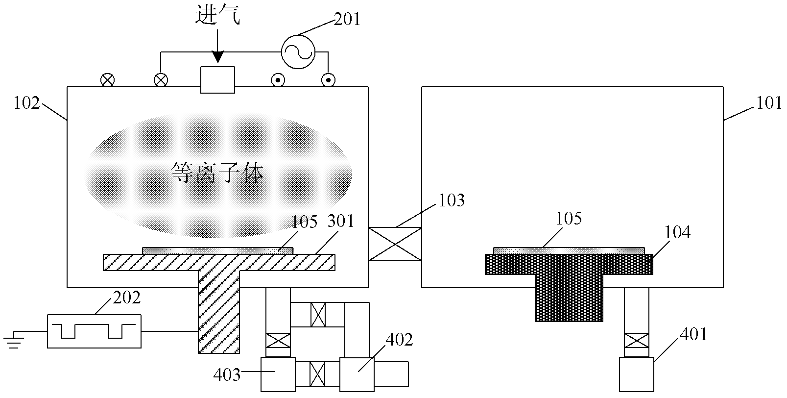
[0020] like figure 1 As shown, this embodiment provides a plasma immersion injection device, including a vacuum chamber, an injection electrode, a power supply part and a vacuum system, wherein the vacuum chamber includes a pre-injection chamber 101 and an injection chamber 102, and the pre-injection chamber The material of 101 and injection chamber 102 is aluminum. A flapper valve 103 is provided between the pre-injection chamber 101 and the injection chamber 102 , and the flapper valve 103 controls the pre-injection chamber 101 to communicate with or separate from the injection chamber 102 . The material of the injection electrode 301 is aluminum, and is disposed in the injection chamber 102 . The power supply part includes a plasma pulsed radio frequency power supply 201 and an injection bias power supply 202. The plasma pulsed radio frequency power supply 201 is used to excite the process gas discharge entering the injection chamber 102 to generate plasma, and the injecti...

Embodiment 2

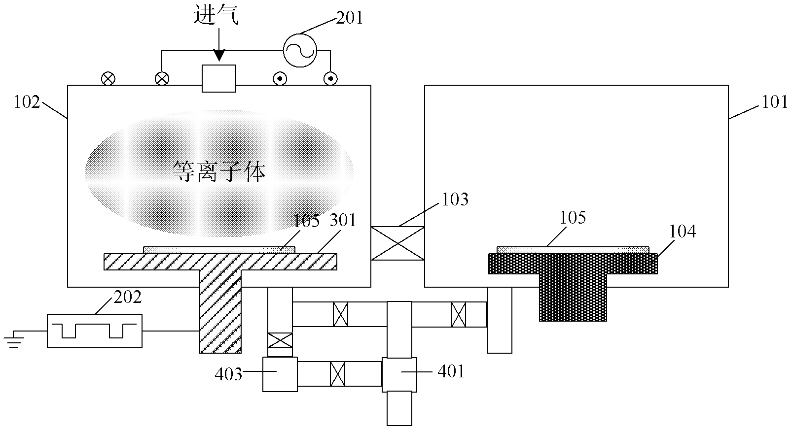
[0026] like figure 2 As shown, this embodiment provides a plasma immersion injection device. In this embodiment, the pre-injection chamber 101 and the injection chamber 102 share a mechanical pump 401, and the connection relationship between other components in this embodiment is the same as the embodiment 1 is the same.

[0027] In this embodiment, when starting the injection, first open the chamber cover of the pre-injection chamber 101, put the substrate 105 to be injected on the robot arm 104, and then close the cover. Under the action of the mechanical pump 401, when the pre-injection chamber is After the vacuum degree in 101 reaches the process requirements, the flapper valve 103 is opened, and the substrate 105 is transported by the robot 104 and placed on the injection electrode 301 of the injection chamber 102; the robot arm 104 returns to the pre-injection chamber 101 and then closes the flapper valve 103; Under the action of the combined pump of the mechanical pum...


PUM


Abstract

The invention relates to the field of semiconductor processing technology and a device, in particular to a plasma immersion injection structure. The plasma immersion injection structure comprises a vacuum cavity, an injection electrode, a power supply part and a vacuum system. The vacuum cavity comprises a pre-injection cavity and an injection cavity. A slide damper is arranged between the pre-injection cavity and the injection cavity. The slide damper controls communication or separation of the pre-injection cavity and the injection cavity. The injection electrode is arranged inside the injection cavity. The plasma immersion injection structure has the advantages of not only achieving shallow junction ion injection of a larger area of substrates, but also greatly shortening vacuum pre-pumping time before injection, and thus improving injection efficiency, but also reducing introduction of foreign ion in the air and reducing injection pollution, and meanwhile reducing corrosion destruction effect of components of water vapor, oxygen and the like in the air from on the inner wall of the injection cavity.

Description

technical field [0001] The invention relates to the field of semiconductor processing technology and equipment, in particular to a plasma immersion implantation device. Background technique [0002] Ion implantation is a process in which high-energy ion beams are implanted into the near-surface region of a substrate to alter surface properties. Ion implantation is widely used in semiconductor fields, such as CMOS processes. Ion implantation is mostly realized by beamline ion implantation (Ion Beam Ion Implantation, IBII) device. The traditional beamline ion implantation device is mainly composed of ion source, mass separator, accelerator, scanning equipment, vacuum system and cooling system. The ion source part generates plasma, and the ions in the plasma are extracted by the mass separator and accelerator to obtain ions of single mass and single energy. The ions of single mass and single energy are injected into the substrate with the aid of the scanning device, and the v...

Claims


Application Information

Patent Timeline
Patent Type & Authority Applications(China)
IPC IPC(8): H01J37/32H05H1/46
Inventor 李超波刘杰屈芙蓉夏洋
Owner 中科九微科技有限公司
Why Eureka
Try Eureka