Alkaline-process smoke halogen removal device and removal method

A halogen and removal technology, applied in the direction of combined devices, separation methods, chemical instruments and methods, etc., can solve the problems of the desulfurization wastewater cannot be recycled, affect the desulfurization effect, increase water consumption, etc., to improve the recycling rate and operation. effect, the effect of reducing water consumption

Pending Publication Date: 2016-05-04
ZHEJIANG ZHENENG TECHN RES INST
View PDF5 Cites 3 Cited by
  • Summary
  • Abstract
  • Description
  • Claims
  • Application Information

AI Technical Summary

Problems solved by technology

When the concentration of fluorine and chlorine in the desulfurization wastewater increases, it will not only affect the desulfurization effect of the wet flue gas limestone-gypsum desulfurization system in the desulfurization absorption tower, but also corrode the pipelines flowing through due to the acidity of the desulfurization wastewater, resulting in Damaged, resulting in desulfurization wastewater can not be recycled, increasing water consumption

Method used


Image

  • Alkaline-process smoke halogen removal device and removal method

Examples


Embodiment 1

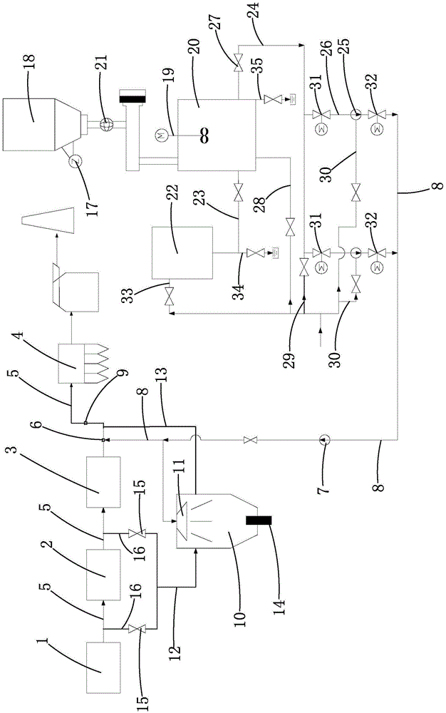
[0021] Embodiment 1: The removal efficiency monitoring mechanism includes an inductor 9 arranged in the tail gas pipeline 5 between the nozzle 6 and the electrostatic precipitator 4, and the slurry preparation mechanism obtains the halogen according to the inductor 9. parameter to adjust the lye parameters. The inductor 9 can be an inductor 9 for testing hydrogen chloride or hydrogen fluoride in the flue gas respectively, and the installation position of the inductor 9 can also be arranged in the tail gas pipeline of the electrostatic precipitator 4 and the desulfurization absorption tower, and can also monitor the flue gas The content of hydrogen chloride and hydrogen fluoride in the medium, and then obtain the data of the efficiency of the atomization injection mechanism to fix the halogen, and provide a basis for the slurry preparation mechanism to adjust the configuration parameters of the lye.

Embodiment 2

[0022] Embodiment 2: The removal efficiency monitoring mechanism includes a detection cabin 10 with a spray chamber, a nozzle 11 located on the top of the spray chamber and connected to the infusion tube 8, and the detection cabin 10 passes through a The intake pipe 12 communicating with the tail gas pipeline 5 introduces the flue gas, and the flue gas is discharged into the tail gas pipeline 5 between the air preheater 3 and the electrostatic precipitator through an exhaust pipe 13. A solid outlet 14 is provided at the bottom of the chamber, and the air inlet pipe 12 and the exhaust pipe are respectively connected to both sides of the spray chamber. By measuring and analyzing the quality and composition of the solid matter discharged from the solid outlet 14, the data on the efficiency of the atomization injection mechanism to fix the halogen is obtained, and provide a basis for the slurry preparation mechanism to adjust the configuration parameters of the lye. One end of the...


PUM


Abstract

The invention relates to an alkaline-process smoke halogen removal device and removal method. The existing boiler tail gas pipeline is not provided with a dedicated system for removing halogen, resulting in high content of halogen in desulphurization waste water. The alkaline-process smoke halogen removal device comprises a slurry preparation mechanism, an atomizing injection mechanism and a removal efficiency monitoring mechanism, wherein alkaline liquor produced by the slurry preparation mechanism is sprayed into a tail gas pipeline disposed between an air preheater and an electric dust collector by virtue of the atomizing injection mechanism, so that the fixing discharging of the halogen is realized. The halogen removal device is additionally arranged on the original tail gas pipeline, the alkaline liquor reacts with hydrogen chloride and halogen fluoride in the smoke to form solid salts, and the solids are discharged out of the tail gas pipeline by utilizing the electric dust collector, so that the halogen content in the smoke is effectively decreased, the halogen content in the desulphurization waste water is further kept at a relatively low level, not only is the operation effect of a desulphurization adsorption tower effectively improved, but also the concentration of fluorine ions and chlorine ions in the desulphurization waste water is reduced, the recycling rate of the desulphurization waste water is increased, the water consumption is reduced, and the corrosion damage of acid substances to the pipeline also can be alleviated.

Description

technical field [0001] The invention relates to the field of thermal power generation, in particular to the field of halogen removal. Background technique [0002] Halogen such as chlorine and fluorine are trace elements in coal samples, which are converted into hydrogen chloride and hydrogen fluoride gas after combustion. These gases will enter the tail gas pipeline along with the boiler exhaust gas, and then pass through the economizer and SCR (Selective Catalytic Reactor) in sequence. , AH (air preheater), ESP (electric precipitator), and FGD (desulfurization absorption tower) are discharged through the chimney. When the flue gas passes through the desulfurization absorption tower, most of the hydrogen chloride and hydrogen fluoride are absorbed and removed, and enter the desulfurization wastewater, resulting in an increase in the concentration of fluorine and chlorine in the desulfurization wastewater. When the concentration of fluorine and chlorine in the desulfurizati...

Claims


Application Information

Patent Timeline
Patent Type & Authority Applications(China)
IPC IPC(8): B01D53/78B01D53/68B01D50/00B01D53/50B01D53/86B01D53/56F23J15/04
CPCB01D50/00B01D53/501B01D53/68B01D53/78B01D53/8625F23J15/04B01D2251/404B01D2251/604B01D2257/204B01D2258/0283
Inventor 施国忠刘春红童小忠张国鑫
Owner ZHEJIANG ZHENENG TECHN RES INST
Why Eureka
Try Eureka