Compressed air energy storage system utilizing two-phase flow to facilitate heat exchange

a technology of energy storage system and compressed air, which is applied in the direction of fluid coupling, container discharging method, servomotor, etc., can solve the problems of inefficiency and limit the economic viability of compressed air energy storage applications, and achieve the effect of high efficiency and facilitate heat exchang

Inactive Publication Date: 2010-12-30
LIGHTSAIL ENERGY
View PDF6 Cites 86 Cited by
  • Summary
  • Abstract
  • Description
  • Claims
  • Application Information

AI Technical Summary

Benefits of technology

[0010]In low-pressure stages, liquid is pumped through an atomizing nozzle into the pressure cell or, in certain embodiments, the cylinder device during the expansion or compression stroke to facilitate heat exchange. The amount of liquid entering the chamber is sufficient to absorb (during compression) or release (during expansion) all the heat associa

Problems solved by technology

However, the process of compressing and decompressing the air typically is inefficient due to thermal and mechanical losses.
Suc

Method used


Image

  • Compressed air energy storage system utilizing two-phase flow to facilitate heat exchange
  • Compressed air energy storage system utilizing two-phase flow to facilitate heat exchange
  • Compressed air energy storage system utilizing two-phase flow to facilitate heat exchange

Examples


Embodiment Construction

[0039]While the present invention will be described with reference to a few specific embodiments, the description is illustrative of the invention and is not to be construed as limiting the invention. Various modifications to the present invention can be made to the preferred embodiments by those skilled in the art without departing from the true spirit and scope of the invention. It will be noted here that for a better understanding, like components are designated by like reference numerals throughout the various figures.

[0040]Single-Stage System

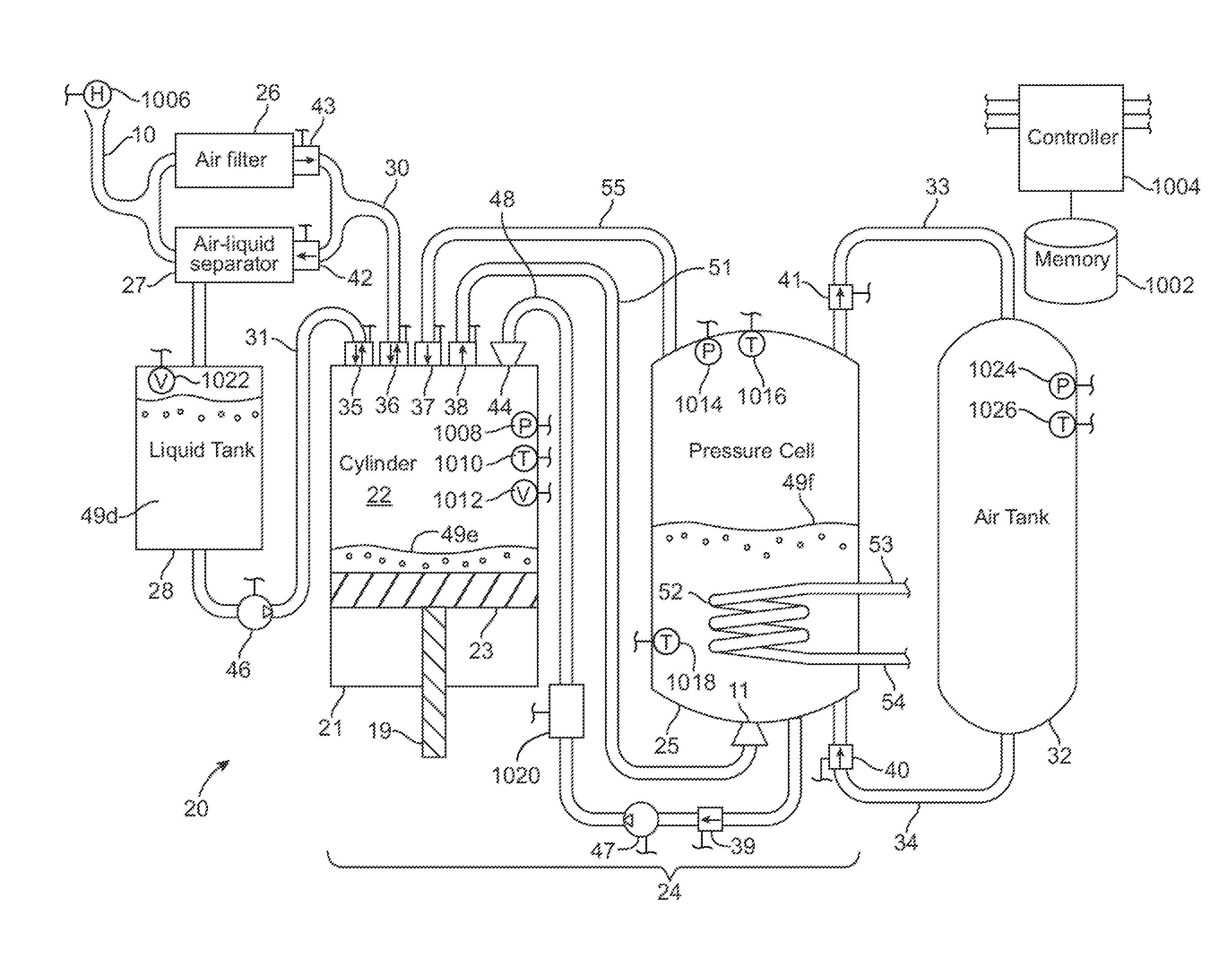
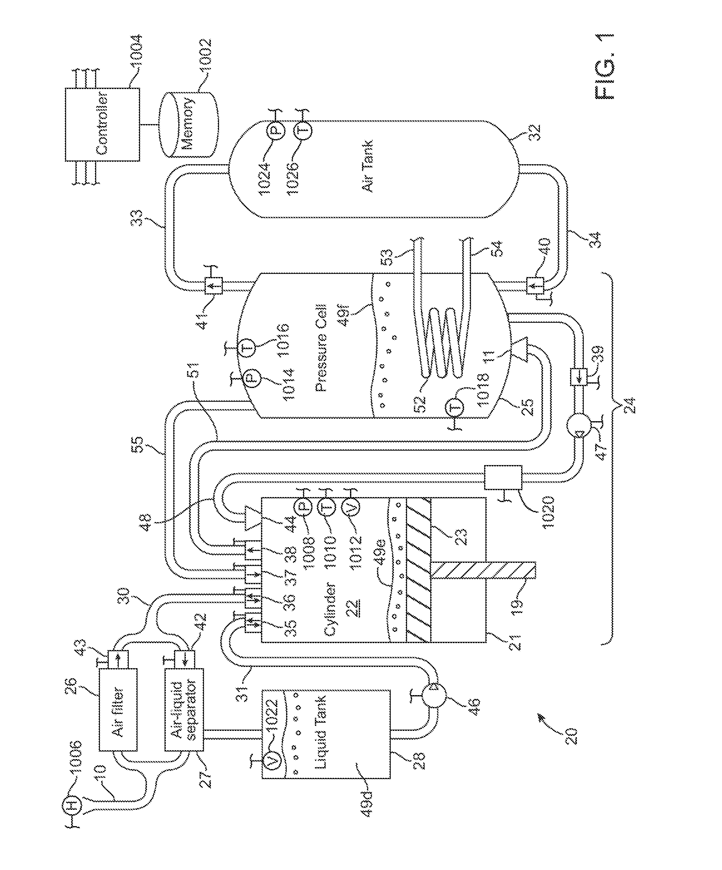
[0041]FIG. 1 depicts the simplest embodiment of the compressed air energy storage system 20 of the present invention, and illustrates many of the important principles. Briefly, some of these principles which improve upon current compressed air energy storage system designs include mixing a liquid with the air to facilitate heat exchange during compression and expansion, thereby improving the efficiency of the process, and applying the same ...


PUM


Abstract

A compressed-air energy storage system according to embodiments of the present invention comprises a reversible mechanism to compress and expand air, one or more compressed air storage tanks, a control system, one or more heat exchangers, and, in certain embodiments of the invention, a motor-generator. The reversible air compressor-expander uses mechanical power to compress air (when it is acting as a compressor) and converts the energy stored in compressed air to mechanical power (when it is acting as an expander). In certain embodiments, the compressor-expander comprises one or more stages, each stage consisting of pressure vessel (the “pressure cell”) partially filled with water or other liquid. In some embodiments, the pressure vessel communicates with one or more cylinder devices to exchange air and liquid with the cylinder chamber(s) thereof. Suitable valving allows air to enter and leave the pressure cell and cylinder device, if present, under electronic control.

Description

CROSS-REFERENCE TO RELATED APPLICATION[0001]The instant nonprovisional patent application claims priority to U.S. Provisional Patent Application No. 61 / 221,487, filed Jun. 29, 2009 and incorporated by reference in its entirety herein for all purposes.BACKGROUND[0002]Air compressed to 300 bar has energy density comparable to that of lead-acid batteries and other energy storage technologies. However, the process of compressing and decompressing the air typically is inefficient due to thermal and mechanical losses. Such inefficiency limits the economic viability of compressed air for energy storage applications, despite its obvious advantages.[0003]It is well known that a compressor will be more efficient if the compression process occurs isothermally, which requires cooling of the air before or during compression. Patents for isothermal gas compressors have been issued on a regular basis since 1930 (e.g., U.S. Pat. Nos. 1,751,537 and 1,929,350). One approach to compressing air efficie...

Claims


Application Information

Patent Timeline
IPC IPC(8): F15B13/00
CPCH02J15/006Y02E60/15F04B41/02F17D1/02H02P9/04F15B1/02Y10T137/6416Y02E60/16F15B1/024Y02E60/00F04B39/0005F04B39/12F15B1/08F15B11/08F15B13/042F15B13/044F15B2211/20538F15B2211/50554F17C5/002F17C13/026F17C13/04
Inventor FONG, DANIELLE A.CRANE, STEPHEN E.BERLIN, JR., EDWIN P.
Owner LIGHTSAIL ENERGY
Why Eureka
Try Eureka