Vacuum angle seat valve

An angle seat valve, vacuum technology, applied in the direction of lift valve, valve details, valve device, etc., to achieve the effect of low cost, light weight, and ease the difficulty of model selection

Active Publication Date: 2010-08-18
JIANGSU CRRC ENVIRONMENT CO LTD
View PDF11 Cites 10 Cited by
  • Summary
  • Abstract
  • Description
  • Claims
  • Application Information

AI Technical Summary

Problems solved by technology

[0003] Previous patents for angle seat valves include (application numbers): 200710171440.3, 200810201418.3, 200810200379.5, 200910131663.6, 200910101411.9. The angle seat valves involved in these patents are all powered by external compressed air. The characteristics of materials and other aspects are quite different from those of the present invention in terms of application fields, working principles, structures, etc.

Method used


Image

  • Vacuum angle seat valve
  • Vacuum angle seat valve

Examples


Embodiment Construction

[0021] The present invention will be further described below in conjunction with the accompanying drawings and embodiments.

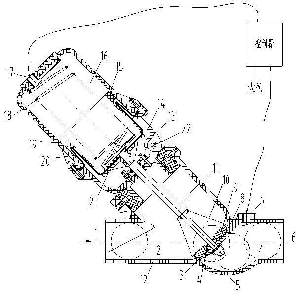
[0022] figure 1 Among them, the vacuum angle seat valve is mainly composed of a valve body 12, a control cavity 15, a free cavity 13, a valve core 4, a spring 18, a rubber diaphragm 20, a piston cylinder 19 and corresponding connecting, fastening and sealing components. 12. The control cavity 15 and the free cavity 13 are sealed at intervals to form the medium cavity 2, the free cavity 14 and the control cavity 16 respectively; usually the inlet 1 of the valve is connected to the medium to be transported, and the outlet 6 is connected to the vacuum source. Due to the action of the spring 18, the free state of the valve is closed, separating the conveyed medium from the vacuum source.

[0023] When the valve needs to be opened to transport medium, another vacuum controller 23 connects the vacuum port 7 with the control chamber interface 17. At this t...


PUM


Abstract

The invention relates to a vacuum angle seat valve which comprises a valve body; one end of the valve body is provided with an inlet, and the other end thereof is provided with an outlet; a valve seat is arranged between the inlet and the outlet; a valve core and the valve seat are arranged in a sealing way; the valve core is connected with a valve rod; after the valve rod passes through a free chamber, the rail end of the valve rod is arranged in a control chamber, and the valve rod is also connected with a reset device; the control chamber is connected with the valve body through the free chamber; a sealing device is arranged between the control chamber and the free chamber; simultaneously, the valve body and the free chamber are separated in the sealing way; and the control chamber is provided with a control chamber interface, the outlet is provided with a vacuum taking port, and the control chamber interface and the vacuum taking port are connected with a vacuum controller. The vacuum angle seat valve is characterized by resource saving, quick on and off, good sealing, no easy blockage, low price, light weight and relatively better reliability and maintenance.

Description

technical field [0001] The present invention relates to a novel vacuum angle seat valve installed in a vacuum conveying system for isolating the conveying medium from the vacuum source. Background technique [0002] Vacuum conveying system is a closed system that uses vacuum to transfer some particles, liquids and other materials to other places. For example, the vacuum sewage system for conveying toilet sewage is a typical vacuum conveying case. Generally, the vacuum inside the vacuum conveying system is in the rough vacuum range, not more than -80KPa, so the valves used in the system can meet the general sealing and pressure-bearing requirements by using normal positive pressure valves. In addition to meeting the general sealing and pressure-bearing requirements, valves used in vacuum conveying systems usually need to meet some special requirements, such as automatic control, frequent opening and closing, rapid opening and closing, good sealing between the valve core and t...

Claims


Application Information

Patent Timeline
Patent Type & Authority Applications(China)
IPC IPC(8): F16K1/00F16K31/12
Inventor 王艳李酉宋彬唐晶殷泉杨晓林
Owner JIANGSU CRRC ENVIRONMENT CO LTD
Why Eureka
Try Eureka