Coupling monitoring method

A monitoring method and array technology, applied in the direction of optical waveguide coupling, etc., can solve the problems of difficult alignment of transmission channels, low product yield, and unsatisfactory accuracy, and achieve simple and convenient operation, improved flattening rate, and improved accuracy Effect

Inactive Publication Date: 2010-08-18
SUZHOU NEW DACHENG TECH DEV
View PDF0 Cites 4 Cited by
  • Summary
  • Abstract
  • Description
  • Claims
  • Application Information

AI Technical Summary

Problems solved by technology

[0004] In the coupling process, it is very difficult to align the fiber array with the transmission channel of the chip because both the waveguide in the chip and the fiber in the fiber array are very small! If you rely on the naked eye to align the optical fiber and the chip waveguide, the accuracy is far from meeting the requirements, which will result in extremely low product yield

Method used


Image

  • Coupling monitoring method
  • Coupling monitoring method

Examples


Embodiment Construction

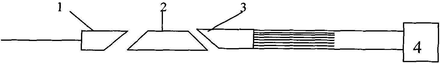
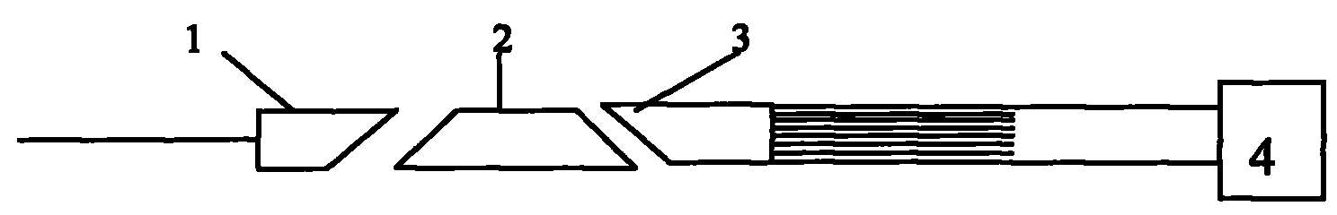
[0011] A coupling monitoring method as shown in the accompanying drawings: (1), input specific light in the single-core fiber array 1; (2), sequentially align the single-core fiber array 1, chip 2, and multi-core fiber array 3; ( 3) Adjust and judge the coupling state by observing the optical instrument 4 connected behind the multi-core optical fiber array 3 .

[0012] In the above monitoring system, because there are many channels at the output end of the optical splitter, it is impossible to monitor the optical fibers at the output end one by one. Because of the characteristics of the fiber array and the chip, the spacing between each channel is 250um or 127um, which is consistent with the spacing of each channel on the chip, so we only need to monitor the two output fibers on the edge of the multi-core FA , when the two channels on the far side are in the best coupling state, then the other channels must be in the best coupling state.


PUM


Abstract

The invention relates to a coupling monitoring method which comprises the following steps that: (1) specific light is input into a single-core optical fiber array; (2) the single-core optical fiber array, a chip and a multi-core optical fiber array are sequentially aligned; and (3) the coupling state is adjusted and judged by observing an optical instrument connected behind the multi-core optical fiber array. The coupling monitoring method has the advantages that the operation is simple and convenient, the alignment precision is improved, the finished product rate is fundamentally improved, and the coupling real-time monitoring effect can be achieved.

Description

Technical field: [0001] The invention relates to a coupling monitoring method. Background technique: [0002] The main feature of the planar waveguide optical splitter is to evenly distribute the input light and play the role of evenly splitting light. The light splitting function is mainly completed on the waveguide chip, and the input and output fibers are made into a fiber array (FA) in order to match the waveguide of the chip. The input end is a one-way or two-way fiber optic array, while the output end has more lines, which can be 8 cores, 16 cores, 32 cores or 64 cores. [0003] The transmission of light requires a medium. Here, the light is transmitted in the optical waveguide of the optical fiber and the chip, so it is necessary to align and bond the optical fiber and the waveguide of the chip to complete the optical transmission path. The above-mentioned alignment and bonding process is called coupling. [0004] In the coupling process, it is very difficult to a...

Claims


Application Information

Patent Timeline
Patent Type & Authority Applications(China)
IPC IPC(8): G02B6/26
Inventor 陈磊
Owner SUZHOU NEW DACHENG TECH DEV
Why Eureka
Try Eureka