Acoustic surface wave radio frequency tag with high coding capacity

A surface acoustic wave and radio frequency tag technology, applied in the field of surface acoustic wave radio frequency tags, can solve the problems of reducing coding capacity, reducing different code capacity, large measurement error, etc., and achieve the effect of large coding capacity

Inactive Publication Date: 2010-08-18
水永安
View PDF5 Cites 12 Cited by
  • Summary
  • Abstract
  • Description
  • Claims
  • Application Information

AI Technical Summary

Problems solved by technology

[0013] (2) Although grouping is not the main feature of U.S. Patent No. 6,966,493, if the 12 groups described in the patent claims are realized, it is necessary to ensure that there is an interval dead zone between two groups that cannot be used for encoding in physical space. This greatly reduces the encoding capacity
As the number of slots increases, the farther the reflective grating position deviates from the reference reflective grating position, the greater the measurement error, thereby reducing reliability, or having to reduce the space size of each group
[0015] (4) The method of temperature compensation is not given
Assuming that the carrier phase of a reflected echo has the fourth quadrant of (+I, -Q) given in the embodiment, after the process of design, label production and actual demodulation, the demodulated phase cannot exceed the fourth quadrant anyway. Four-quadrant range, otherwise it will cause label decoding error
However, the change of the working temperature of the label often makes all the measured phases of the reflected signal deviate from the design value.
As the temperature range increases, if the temperature compensation is not set or the temperature compensation is not set properly, it may cause the measured phase to exceed the fourth quadrant, resulting in bit errors
As a result, on the one hand, it is necessary to set a sufficiently large distance between the slots in its design so as to drastically reduce the different code capacity; on the other hand, its usable temperature range is greatly limited

Method used


Image

  • Acoustic surface wave radio frequency tag with high coding capacity
  • Acoustic surface wave radio frequency tag with high coding capacity
  • Acoustic surface wave radio frequency tag with high coding capacity

Examples


Embodiment 1

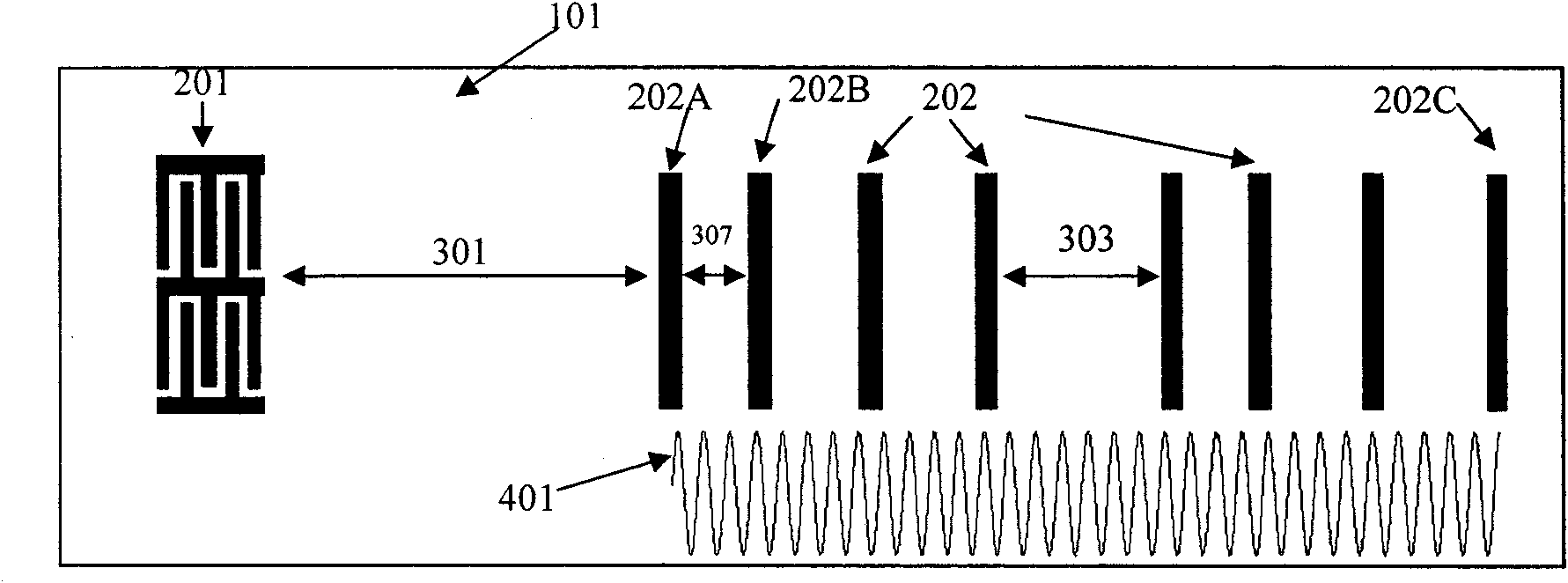
[0036] Such as figure 1 shown, at 128°-YXLiNbO 3 The surface acoustic wave radio frequency tag 1 with the encoding method proposed by the patent of the present invention is manufactured on the piezoelectric substrate 101 . The radio frequency tag 1 includes an interdigital transducer 201 and several reflective grids 202 (there may be 2 to 40 reflective grids) arranged behind the interdigital transducer. Transducer 201 as figure 1 As shown, conventional interdigital transducers are cascaded to obtain better impedance matching. The frequency range of the wireless inquiry signal is 920-925MHz. The reflective grids 202 can be arranged in one or more rows. The position between these reflective gratings 202 is measured by the period of the surface acoustic wave 401 whose echo is at the center frequency. (Twice the phase delay at the corresponding central frequency of the reflective grating position.) The phase delay time between reflective gratings 202A, 202B, (or plus 202C) is...

Embodiment 2

[0043] The material of the piezoelectric substrate is the same as in Embodiment 1, and the length of the substrate is 11.1 mm. The positions of the three reflection grids of the temperature standard used are also the same as those in Example 1. The selected value of Δn, K min value and K max The value of is also the same as in Example 1. In this embodiment, the IDT 201 is designed as a low-loss single-phase unidirectional transducer. The encoding region 700A between the reflective grating 202B and the reflective grating 202C is still k a Δn=434Δn. The difference is that after 202C, there is a coding area 700B at the end of the substrate, where a reflective grid for code information can be placed. The transducers used and the blind zone are also the same as in the embodiment. The usable time length T can be calculated as 5087 cycles when the substrate length is 11.1 mm similarly to the embodiment. Then the size of the information space in the encoding region 700B is k T...

Embodiment 3

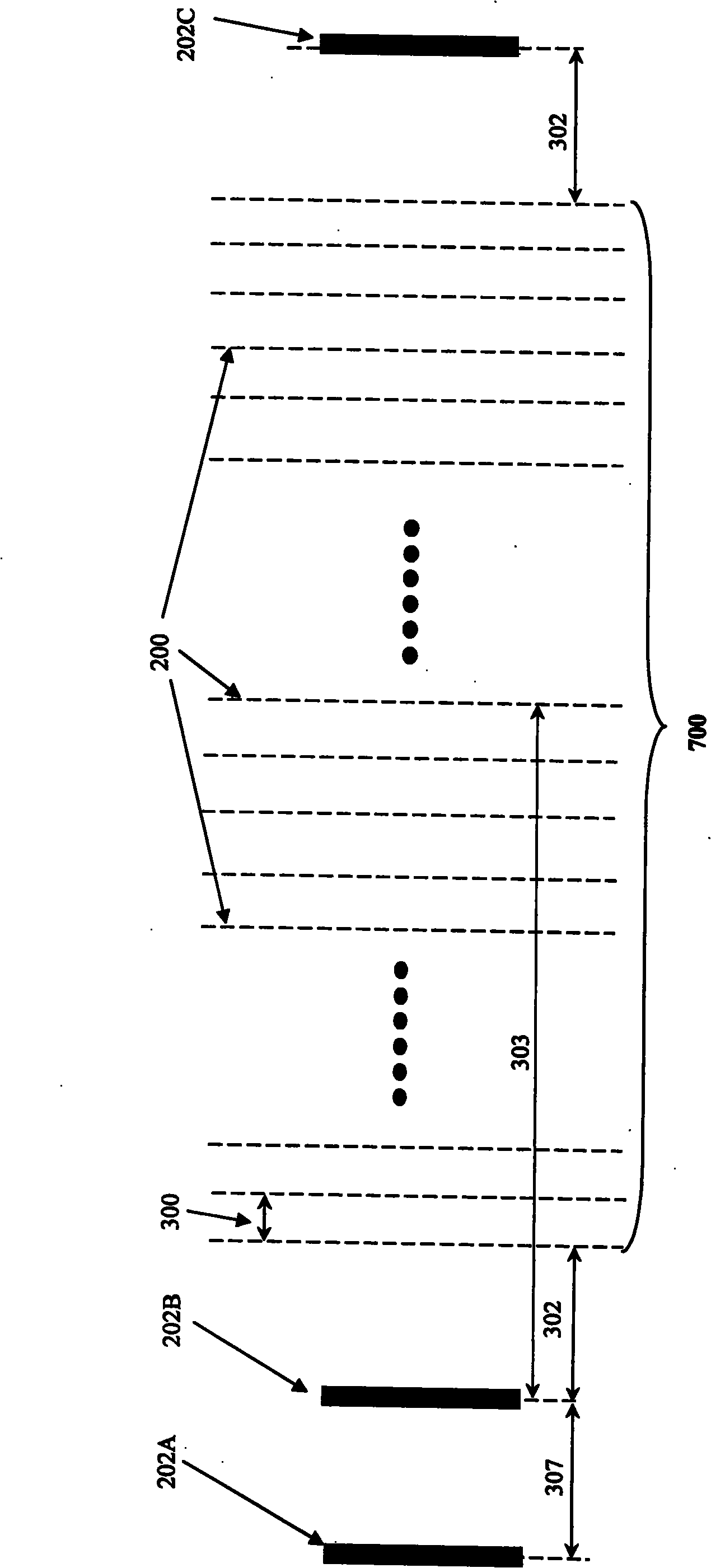
[0045] The piezoelectric substrate material is the same as in Example 1. In this embodiment, the center frequency of the device is 2.44GHz, and the bandwidth is 40MHz. The interdigital transducer 201 is designed as a low-loss single-phase unidirectional transducer based on high-order harmonics. The values ​​between the positions 200 that allow the placement of reflective gratings are Δn = 6.1 periods. The minimum phase delay time interval value of adjacent pulses 302 is n min =12Δn, the maximum phase delay time interval value of adjacent pulses 303 is n max =24Δn, the size of the encoding region 700 space is k T Δn=172Δn. Can obtain code capacity by the encoding method of this patent and be 72243061840, C=log 2 72243061840 = 36.07.


PUM


Abstract

The invention relates to an acoustic surface wave radio frequency tag which is characterized in that an interdigital transducer is manufactured on a piezoelectric substrate, and a series of reflecting gratings are arranged behind the interdigital transducer; the reflecting gratings can be arranged in one row or multiple rows; the time interval from the interdigital transducer to the reflecting pulse of the first reflecting grating is set as a blind area, and the position of the first reflecting grating is determined according to the size of the blind area; in order to correct the influence ofthe uncertain environment temperature, two or three reflecting gratings are arranged generally, wherein one or two phase delay time intervals among the reflecting gratings are accurately known under the specific standard temperature and are constants irrelevant to code values, and each phase delay time interval between other adjacent reflecting gratings is used for representing different tag codes; and the phase delay time intervals among the reflecting gratings are limited, are not definitely used for directly representing code values, and can be possibly used for self-checking, self-correction or anti-collision and other purposes of coded data. The invention can obtain maximal coding capacity under the same information space and frequency bandwidth.

Description

technical field [0001] This patent relates to surface acoustic wave radio frequency tags. Background technique [0002] Radio Frequency Identification (RFID, Radio Frequency Identification) technology is a technology that applies non-contact tags, which automatically identify target objects and obtain relevant data through radio frequency signals. It is an important practical technology to adapt to the development of information technology and information society. It is used in intelligent management in many fields such as automatic toll collection of expressways, logistics management, automatic parcel sorting of postal aviation, storage and book management, animal husbandry monitoring and management, and vehicle anti-theft. It has great application prospects. In order to achieve a single tag number for any item in the world, the tag needs to implement 64-bit, 96-bit or even 128-bit encoding. [0003] RFID tags using Surface Acoustic Wave (SAW) technology is a radio freque...

Claims


Application Information

Patent Timeline
Patent Type & Authority Applications(China)
IPC IPC(8): H03H9/64G01V15/00
Inventor 水永安韩韬
Owner 水永安
Why Eureka
Try Eureka