Novel large-power cavity separating type cabinet frame

A high-power, cabinet technology, applied in electrical equipment shell/cabinet/drawer, cooling/ventilation/heating transformation, circuit layout on support structure, etc. Occupation and other problems to achieve the effect of overcoming the difference in volume and solving the inefficiency of convection heat transfer

Inactive Publication Date: 2010-08-18
SAMIL POWER
View PDF4 Cites 4 Cited by
  • Summary
  • Abstract
  • Description
  • Claims
  • Application Information

AI Technical Summary

Problems solved by technology

The traditional cabinet structure generally installs magnetic components side by side horizontally, and then installs high-power electrical modules and electrical functional modules on the YZ plane with sheet metal parts on the upper part of the cabinet; when the traditional cabinet structure is applied to high-power electric products, it brings two One problem is that the large space at the bottom is occupied by large and heavy magnetic components such as transformers and inductors, resulting in a small space on the same side of the YZ plane on the upper part of the cabinet. The electrical module components on the same electrical circuit are due to volume differences and YZ planes. The space on the same side is too small to complete the installation on the same side of the YZ plane, and it needs to be scattered on the front and rear sides of the cabinet (such as figure 1 ), resulting in complex front and rear wiring, difficult installation, and relatively low production efficiency
For example: the large current power line of the main circuit has a large minimum bending radius and a thick wire diameter. Because the electrical components of the same main circuit are randomly distributed on the front and rear sides of the YZ plane, the wiring is difficult, the installation is complicated, and the production efficiency is low; Yes: The inside of the cabinet is generally forced air cooling, that is, the fan on the top of the cabinet draws the external cold air from the bottom, and the cold air passes through the main heat sink on the upper part of the cabinet to complete the convective heat exchange, taking away the heat generated by the normal operation of the electrical modules with high power consumption
In the traditional cabinet structure, the external cold air needs to pass through magnetic components with large volume and large heat dissipation area such as transformers and inductors, absorb part of the heat, and then pass through the main heat sink on the upper part of the cabinet to complete convective heat transfer, resulting in convective heat transfer of the main heat sink. The efficiency is not high, and the cooling cost of the whole machine increases

Method used


Image

  • Novel large-power cavity separating type cabinet frame
  • Novel large-power cavity separating type cabinet frame
  • Novel large-power cavity separating type cabinet frame

Examples


Embodiment Construction

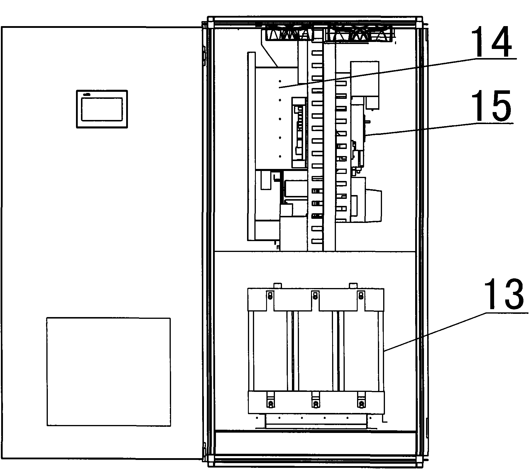
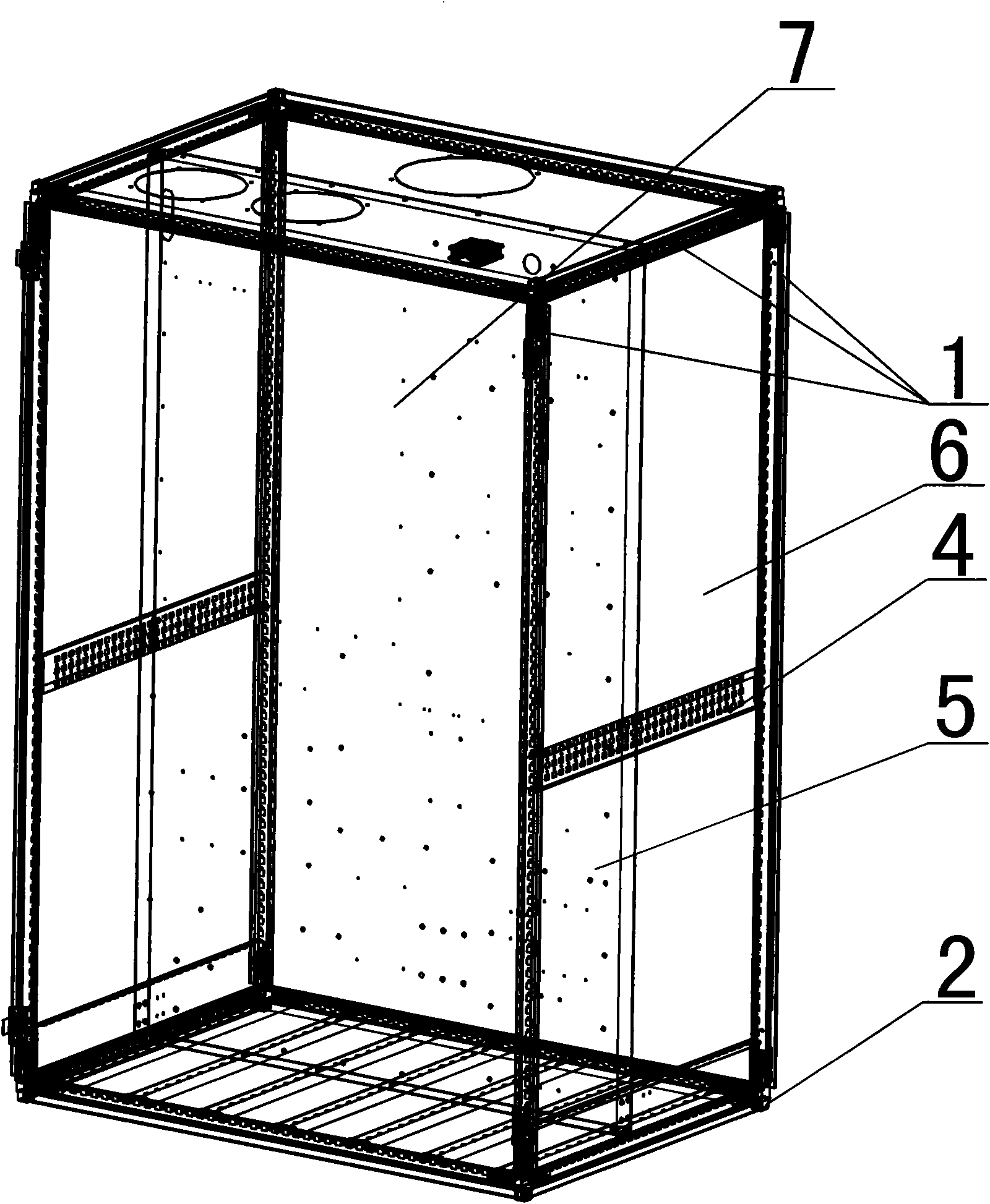
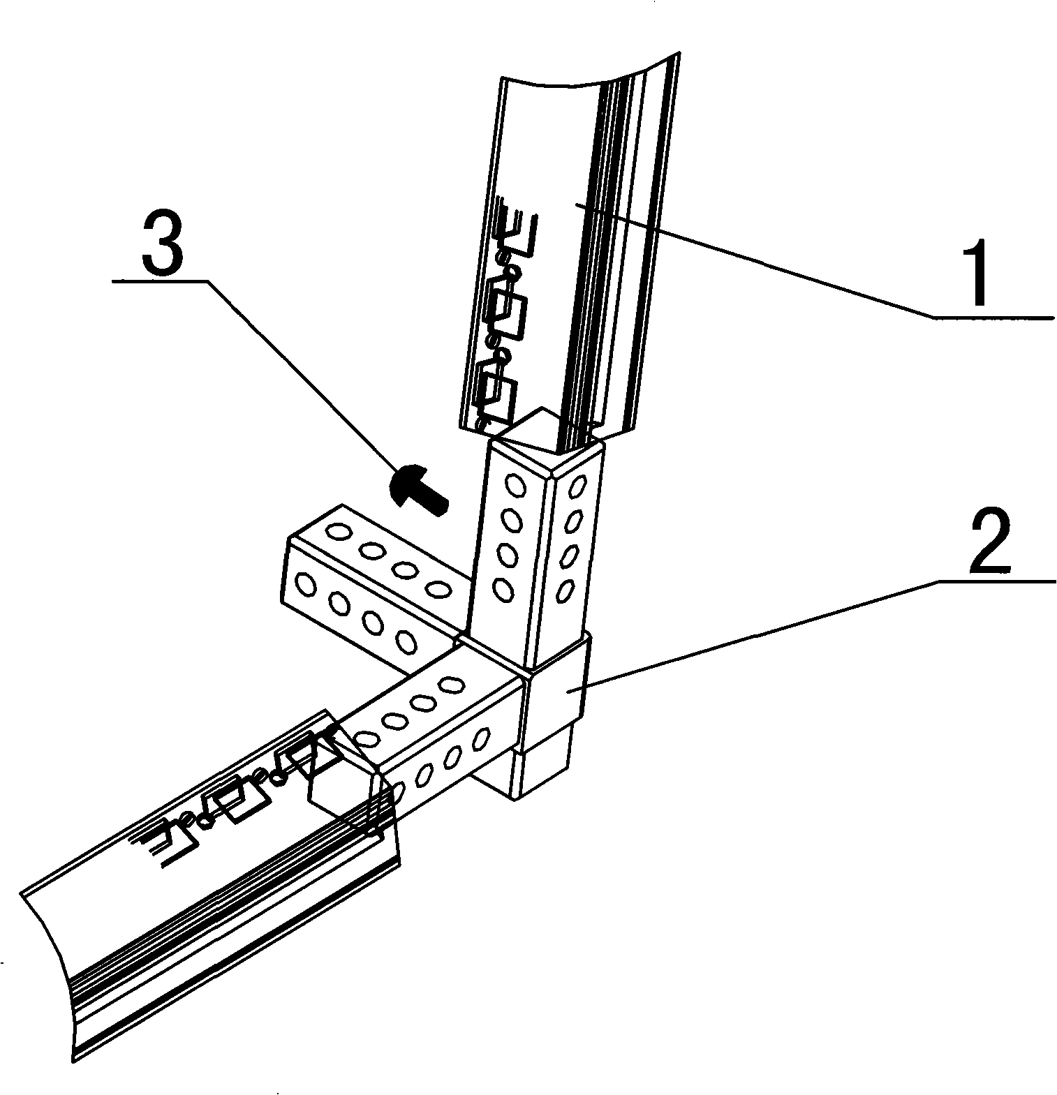
[0016] Such as Figure 1-6 As shown, the novel high-power sub-cavity cabinet frame of the present invention includes a cabinet frame body composed of twelve standard columns 1, triangular brackets 2 and M5 self-tapping screws 3. The middle part of the columns 1 passes through M5 self-tapping screws 3 are fixed on the steel beam 4, and the inner cavity of the frame is vertically laid with a 2mm-thick middle partition 5, which is respectively locked on four steel beams 4 parallel to the Y direction by M5 self-tapping screws 3 and inside the cabinet. Two independent electrical cavities are formed, that is, the electromagnetic cavity 6 and the electrical functional cavity 7; the bottom end of the column 1 is provided with a triangular bracket 2 and connected to the adjacent column 1 through the bracket. The electromagnetic cavity 6 is used to install magnetic elements 13, and the electrical function cavity 7 is used to install high-power consumption electrical module components 14...


PUM


Abstract

The invention relates to a novel large-power cavity separating type cabinet frame which comprises a cabinet frame body formed by tightly connecting twelve standard upright posts, a tripod and tapping screws, wherein the middle parts of the upright posts are fixed on a steel beam through the tapping screws; middle clapboards are vertically laid in the inner cavity of the frame body; and two independent electrical cavities, namely an electromagnetic cavity and an electrical function cavity are formed in the cabinet. The invention has the advantages that by adopting the novel large-power cavity separating type cabinet frame, three types of electrical components are separated at the middle part of the cabinet by middle clapboards, thereby solving the problems of complex wiring, large installation difficulty and relatively lower production efficiency of the traditional cabinet structure; and by forming two independent electrical cavities in the cabinet, outside cold air does not need to pass through magnetic components and directly completes heat convection with the other two types of electrical components, thereby solving the problems of low heat convection efficiency of main radiating fins and increase of radiating cost of the complete machine.

Description

technical field [0001] The invention relates to a cabinet structure of electric power products, in particular to a novel high-power sub-cavity cabinet frame. Background technique [0002] At present, high-power power products are generally composed of three types of components, namely transformers, inductors and other magnetic components with large volume, weight and high calorific value, electrical modules with high power consumption such as insulated gate bipolar power tubes, control boards, input and output Electrical functional modules such as filters. The traditional cabinet structure generally installs magnetic components side by side horizontally, and then installs high-power electrical modules and electrical functional modules on the YZ plane with sheet metal parts on the upper part of the cabinet; when the traditional cabinet structure is applied to high-power electric products, it brings two One problem is that the large space at the bottom is occupied by large an...

Claims


Application Information

Patent Timeline
Patent Type & Authority Applications(China)
IPC IPC(8): H05K5/00H05K7/08H05K7/20
Inventor 催佩聚牟英峰郭伟
Owner SAMIL POWER
Why Eureka
Try Eureka