Laminar flow water cooling device and control method

A technology of cooling device and control method, which is applied in the directions of temperature control, metal rolling, manufacturing tools, etc., can solve the problems of wasting cooling water, reducing the temperature drop at the edge of strip steel, unfavorable production resource saving, etc., so as to ensure the plate shape, Avoid waste and reduce the effect of temperature drop

Active Publication Date: 2010-08-25
BAOSHAN IRON & STEEL CO LTD
View PDF1 Cites 5 Cited by
  • Summary
  • Abstract
  • Description
  • Claims
  • Application Information

AI Technical Summary

Problems solved by technology

This method adopts the method for shielding the edge of the laminar flow cooling header, and provides a solution to the problem that the temperature of the edge of the strip is greatly reduced, but there are also shortcomings in this method. Obviously, the shortcoming of this prior art is that : When producing narrow strip steel, a large amount of cooling water is wasted in vain, which is not conducive to the saving of production resources
[0010] The inventor envisages developing a laminar flow cooling device and cooling method, which can establish a gap laminar flow corresponding to the width of the strip channel according to the cooling process requirements of different widths of the strip, and realize the corresponding change in the width of the laminar flow cooling area. Thereby adjusting the area of ​​cooling water in the width direction of the channel, reducing the temperature drop at the edge of the strip, and ensuring the uniformity of the shape, mechanical properties, temperature and phase transition of the strip in the width direction; and the existing edge shielding technology Different, while achieving the same effect, it can also avoid the waste of cooling water resources. After online search, no identical or similar patented technology has been found so far.

Method used


Image

  • Laminar flow water cooling device and control method
  • Laminar flow water cooling device and control method
  • Laminar flow water cooling device and control method

Examples


Embodiment Construction

[0047] A preferred embodiment of the present invention will be specifically introduced below in conjunction with accompanying drawings 1-4.

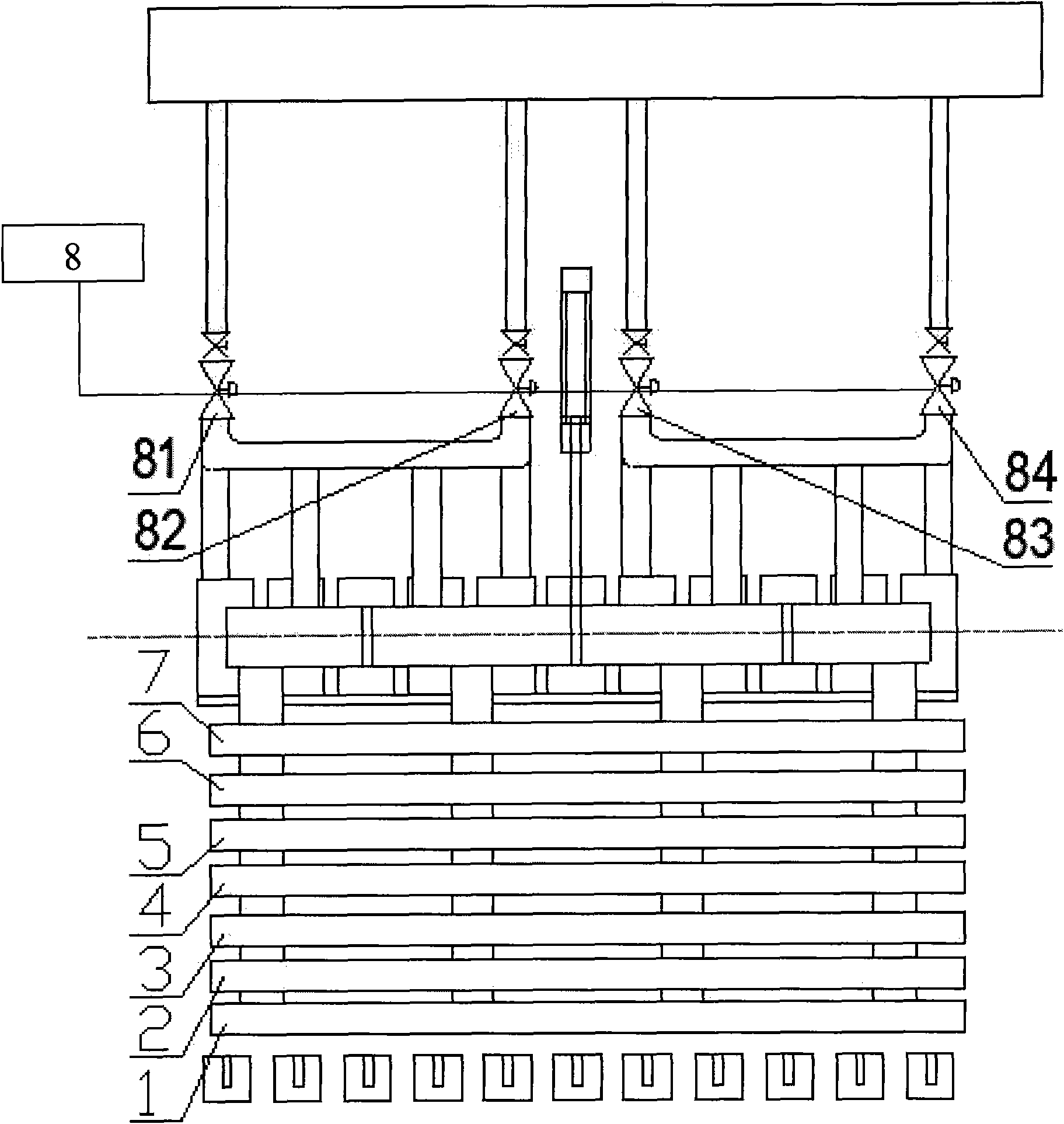
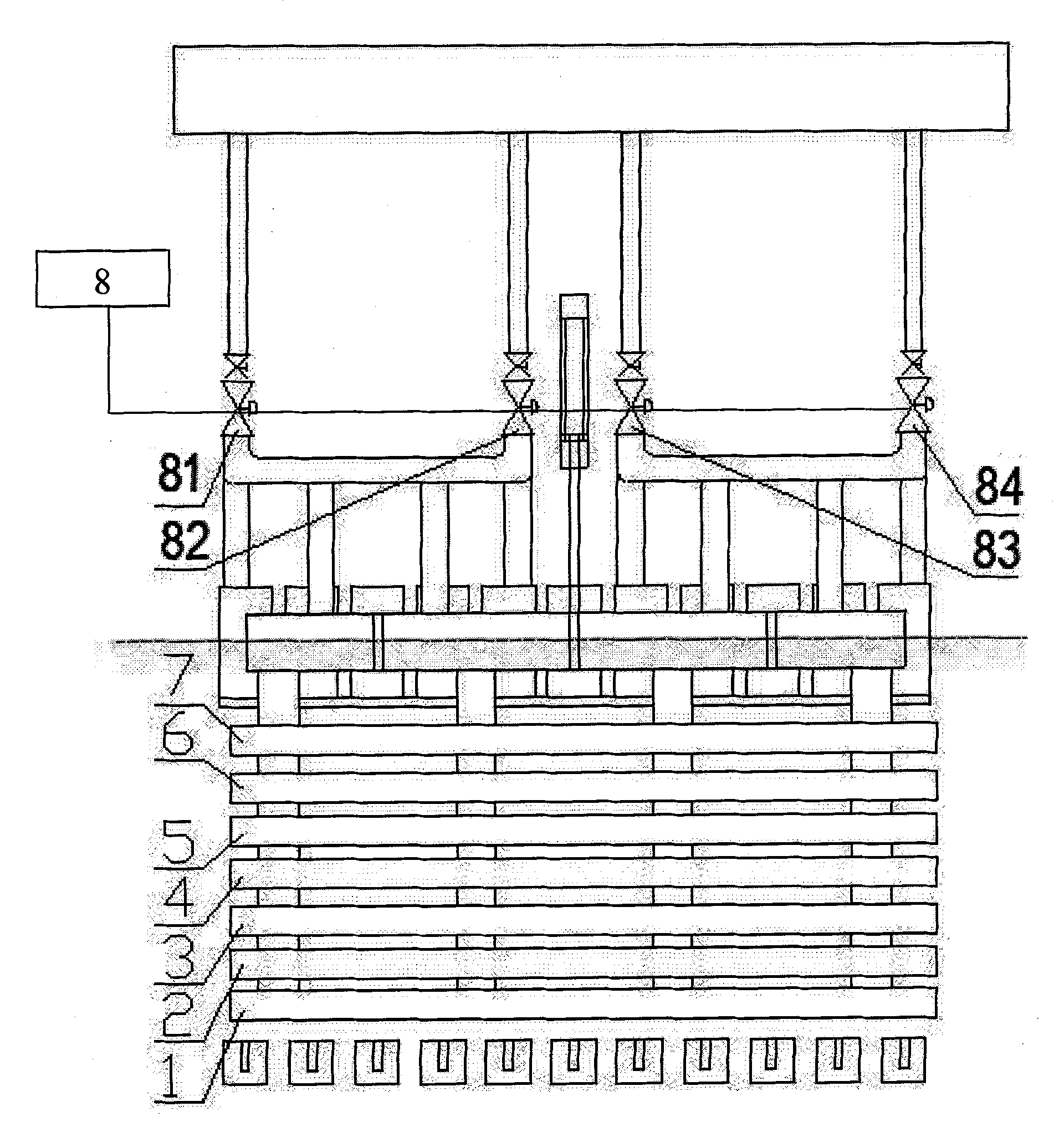
[0048]As shown in Figure 1, the present invention is installed vertically on the steel strip advancing direction, and the water storage pipes 1-7 are equally spaced, and the central water storage pipe 4 is controlled by a water valve 81, and the water storage pipes 3, 5 is controlled by a water valve 82 at the same time, the water storage pipes 2 and 6 near the outside of the water storage pipes 3 and 5 are controlled by a water valve 83 at the same time, and the water storage pipes 1 and 7 near the outside of the water storage pipes 2 and 6 are simultaneously controlled by a water valve 84 . A control unit 8 is respectively connected to the water valves 81-84 to control the opening and closing of each water valve.

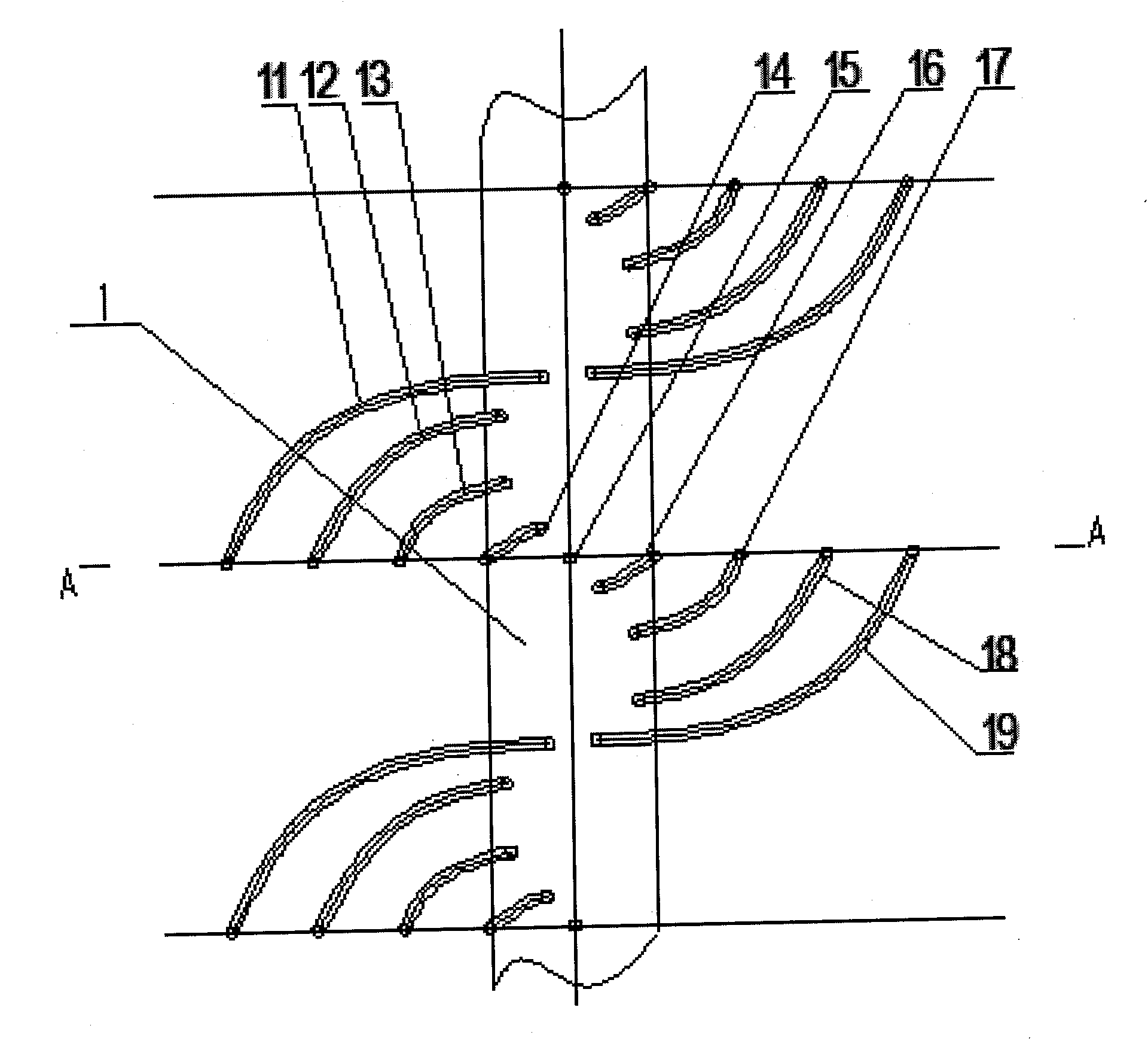
[0049] As shown in Figures 2 and 3, several groups of goosenecks are spirally connected on both sides of each water stora...


PUM


Abstract

The invention relates to a laminar flow water cooling device and a control method. The laminar flow water cooling device comprises a plurality of water storage pipes, the arrangement direction of the water storage pipes is the same as the operating direction of strip steel, the water storage pipes are symmetrically distributed, water inlet ends of the water storage pipes are respectively provided with a water valve, and bodies of the water storage pipes are respectively provided with a plurality of cooling water pipes distributed at equal intervals. The control method comprises the following steps of: (1) starting; (2) acquiring width data of the strip steel from an upper PLC; (3) calculating the width of cooling water; (4) using a control unit to send opening command to all the water valves; (5) using an electromagnetic valve to control the water valves according to the opening command; (6) judging whether the strip steel throws the tail; (7) leading the laminar flow water cooling device to stop working; and (8) finishing laminar flow cooling control process. The invention adjusts the area of the cooling water along the channel width direction according to the cooling technique requirements of different widths of the strip steel, reduces the temperature reduction at the side of the strip steel, and guarantees the profile shape, the mechanical performance, the temperature and the uniformity of phase change along the width direction of the strip steel.

Description

technical field [0001] The invention relates to a hot rolling laminar cooling technology in the field of metallurgy, in particular to a hot rolling laminar cooling device and a cooling control method. Background technique [0002] The laminar flow cooling device is used in the hot rolling and continuous rolling mill production lines of iron and steel enterprises. Its main function is to quickly cool the strip steel exported from finish rolling according to the target temperature set by coiling to ensure the product performance of the strip steel. [0003] Taking the hot rolling mill as an example, its laminar flow cooling device has a total of 76 sets of cooling headers (corresponding to one set of upper and lower). Among them, the first 68 groups are the main cooling section, and the last 8 groups are the refined cooling section. It is generally divided into several cooling zones, and each cooling zone has its own main cooling section and the cooling section of the fine co...

Claims


Application Information

Patent Timeline
Patent Type & Authority Applications(China)
IPC IPC(8): B21B45/02B21B37/76
Inventor 王军
Owner BAOSHAN IRON & STEEL CO LTD
Why Eureka
Try Eureka