Driving component and using method thereof

A technology of driving components and linear motion, which is applied in the direction of engine components, transmission devices, fluid transmission devices, etc., can solve the problems of inability to output counterclockwise torque, inconvenient use of the drive device, and inability to output different pistons, etc., to achieve light weight, The effect of compact structure and balanced structure

Inactive Publication Date: 2010-08-25
史易兰商务咨询(上海)有限公司
View PDF5 Cites 4 Cited by
  • Summary
  • Abstract
  • Description
  • Claims
  • Application Information

AI Technical Summary

Problems solved by technology

If the piston cannot move closer to the output shaft, it cannot output counterclockwise torque, and cannot output counterclockwise torque when the piston moves away from the output shaft
Since the piston of the drive device moves in one direction, it can only output torque in one direction, and cannot output torque in different directions when the piston moves in one direction, which makes the existing drive device inconvenient to use and expensive high

Method used


Image

  • Driving component and using method thereof
  • Driving component and using method thereof
  • Driving component and using method thereof

Examples


Embodiment 1

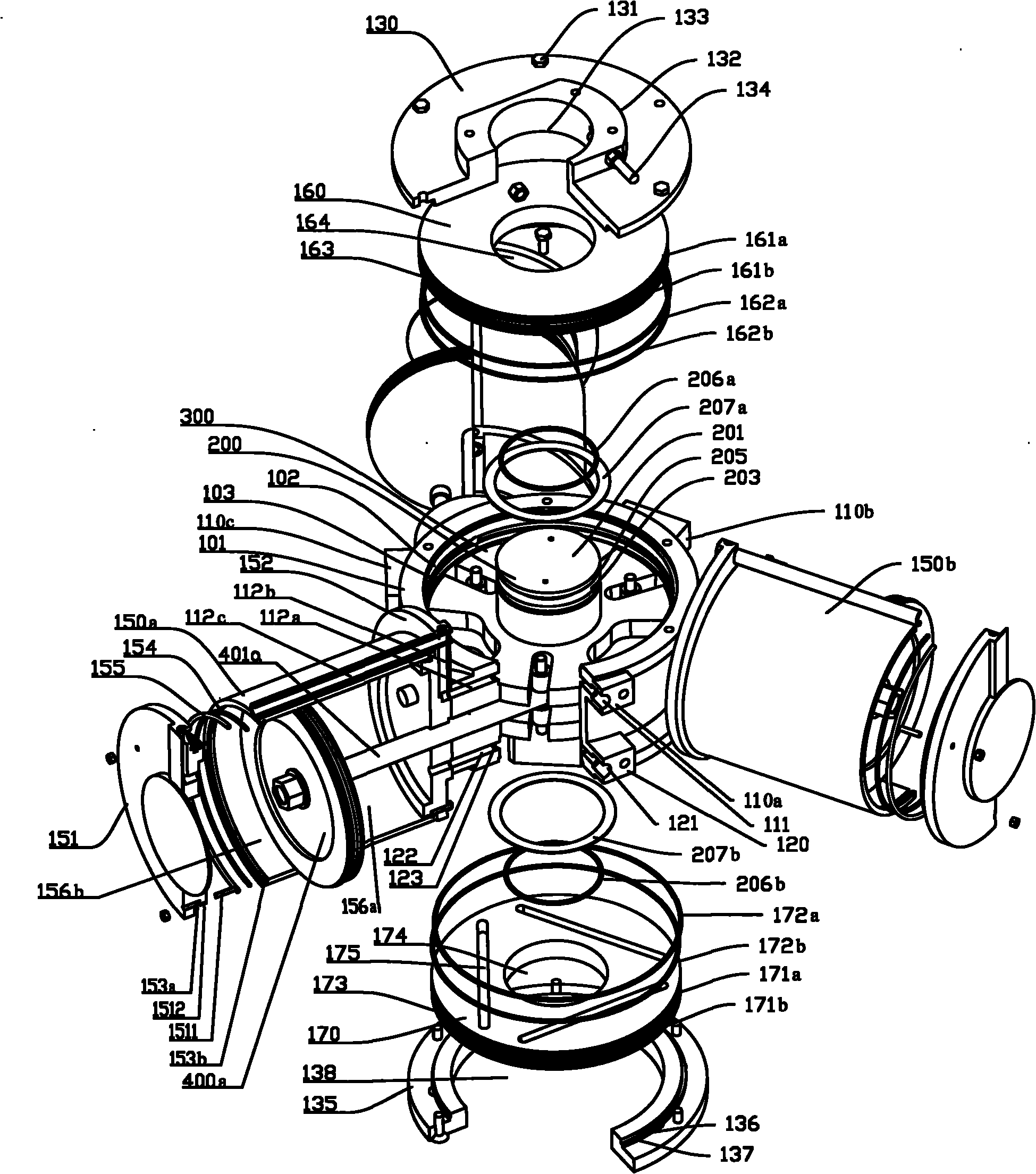
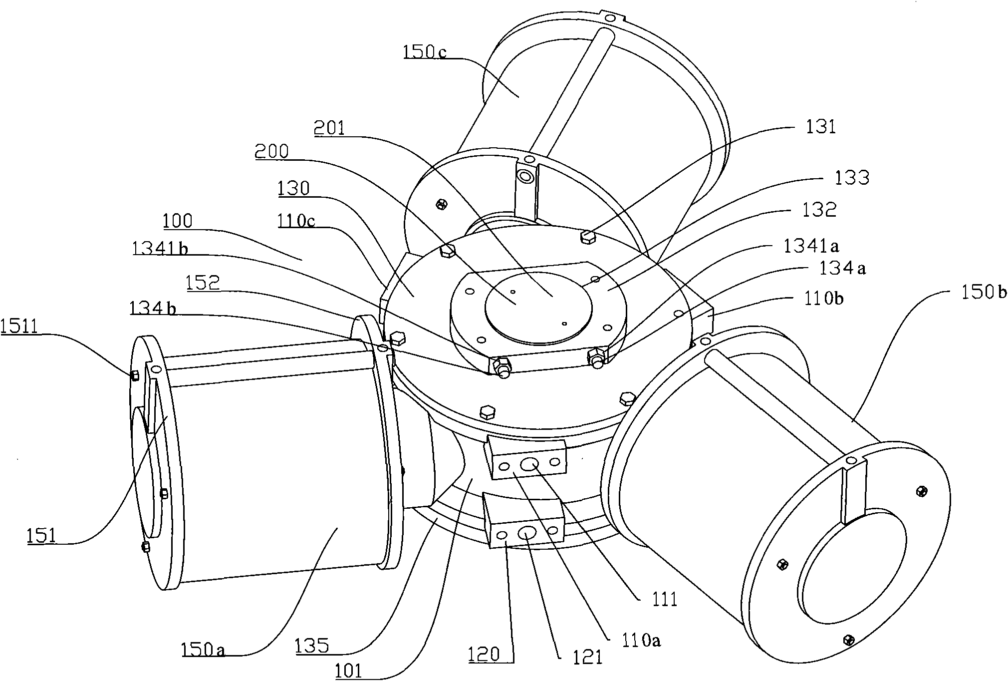
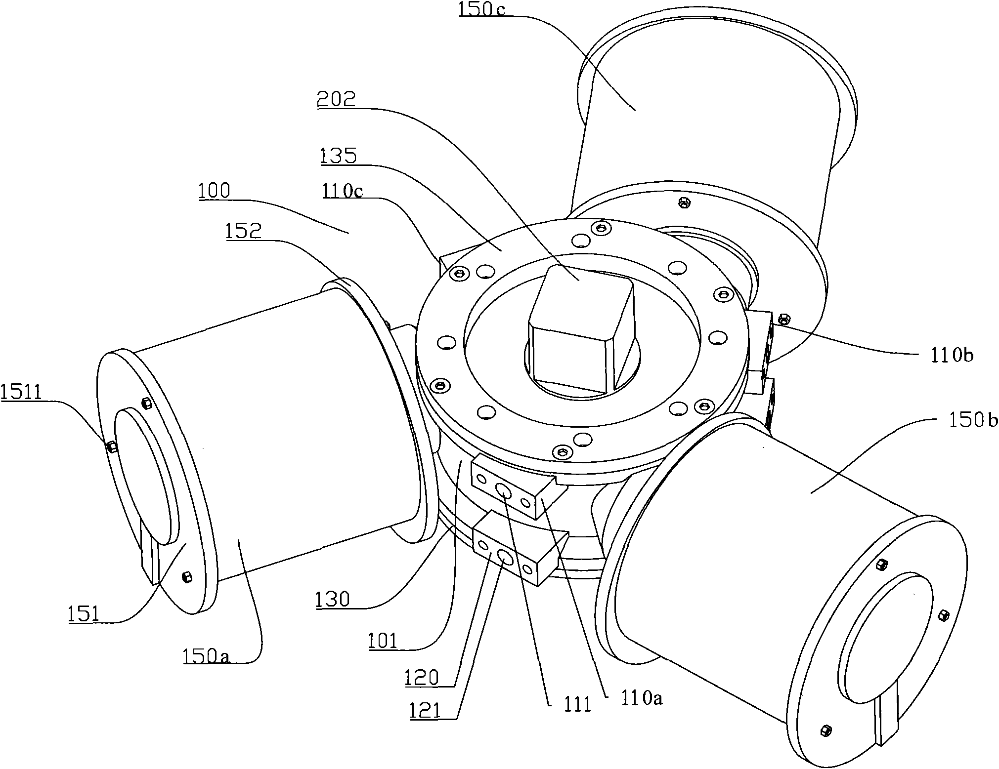
[0111] Fig. 1 is a schematic diagram of the appearance structure of the present invention, and Fig. 2 is a schematic diagram of Fig. 1 turned over 180 degrees. As shown in FIG. 1 and FIG. 2 , the drive assembly includes a casing 100, and the casing 100 includes a first cylinder 101 and three second cylinders (150a, 150b, 150c) with horizontal holes. The three second cylinders (150a, 150b, 150c) have the same structure, and the three second cylinders (150a, 150b, 150c) are equicircumferentially distributed on the outer wall of the first cylinder 101 .

[0112]A top cover 130 and a bottom cover 135 are respectively mounted on two ends of the first cylinder 101 . The top cover 130 is mounted on the top of the first cylinder 101 via bolts 131 . A positioning block 132 is disposed on the top cover 130 , and the positioning block 132 protrudes from the top cover 130 . The positioning block 132 is provided with a first through hole 133 . One end of the output shaft 200 is located ...

Embodiment 2

[0144]Fig. 14 is a schematic structural diagram of Embodiment 2 of the present invention. As shown in FIG. 14 , the difference from Embodiment 1 is that the second end 202 of the output shaft 200 does not have a cube adapter, but adopts an eccentric cylinder 202B and a cylinder 202A connected in sequence as the adapter. The eccentric cylinder 202B is located between the housing 200 and the cylinder 202A. All the other structures are the same as in Example 1. FIG. 15 is a half-sectional view of the output shaft 200 in Embodiment 2 and a schematic view of a method of use. The adapter 500 of the valve in Fig. 15 is also a half-sectional view. As shown in FIG. 15 , the valve adapter 500 is provided with a circular hole 501 matching with the cylinder 202A and an eccentric circular hole 502 matching with the eccentric cylinder 202B. When using the output shaft 200 to drive the valve, the cylinder 202B of the output shaft 200 can be inserted into the circular hole 501 of the adapt...

Embodiment 3

[0148] Fig. 16 is a cross-sectional view of one of the second cylinders 150a of Embodiment 3. As shown in Fig. 16, the difference between it and Embodiment 1 is that a spring 157 is arranged in the second part 156b of the inner chamber of the second cylinder 150a. , both ends of the spring 157 are respectively connected to the end cover 151 and the piston 400a. After the high-pressure fluid enters the first part 150a of the inner cavity of the second cylinder 150a, the piston 400a is pushed to move to the left, that is, when moving away from the roller (not shown), the piston 400a compresses the spring 157, and the spring 157 is compressed. Generate potential energy. If there is always high-pressure fluid in the first part 150a of the inner cavity of the second cylinder 150a, the spring 157 can always be in a compressed state. After the high-pressure fluid in the first part 150a of the inner cavity of the second cylinder 150a is emptied, the potential energy of the spring 157...


PUM


Abstract

The invention discloses a driving component, which is characterized by comprising a shell, an output shaft and a linear motion device, wherein a vertical hole and a horizontal hole are arranged on the shell; the output shaft is rotatably installed in the vertical hole; the linear motion device is installed in the horizontal hole in a reciprocating motion mode; and the linear motion device is connected with the output shaft in a mode capable of converting the linear motion of the linear motion device into rotary connection of the output shaft. The fluid driving component of the invention has compact structure, stable operation, strong transfer torque, light weight, long service life and strong connectivity, can output torques with two different rotation directions under the condition that the linear motion device moves in one direction, has high conformability, high efficiency, structural balance and vibration resistance, can be used for connecting various valves easily, and is especially suitable for operational conditions with high vibration, such as a susceptible area of earthquake and the periphery of an engine.

Description

technical field [0001] The present invention relates to a driving assembly and a method of using the same. Background technique [0002] In many occasions, it is necessary to use valves to control the flow of pipelines, such as high-pressure gas or oil pipelines. In high-pressure gas or oil pipelines, due to the internal high pressure, it is necessary to use a driving device to control the opening and closing of the valve. In some other application occasions, the output torque of the driving device is also required. [0003] In a pipeline, multiple valves are often used. The working methods of the valves are not exactly the same. Some valves require the valve stem to be rotated clockwise to open the valve; otherwise, the valve stem needs to be rotated counterclockwise to close the valve. Some valves require the valve stem to be rotated counterclockwise to open the valve; otherwise, the valve stem needs to be rotated clockwise to close the valve. In the fluid drive device...

Claims


Application Information

Patent Timeline
Patent Type & Authority Applications(China)
IPC IPC(8): F16H47/00F16K31/122F16K31/53
Inventor 束建超
Owner 史易兰商务咨询(上海)有限公司
Why Eureka
Try Eureka