Temperature-control variable-pressure heat accumulator control system and control method thereof

A control system and heat accumulator technology, applied in heat storage equipment, heat exchanger types, indirect heat exchangers, etc. Stable pressure, reducing equipment accident rate and high output

Active Publication Date: 2010-08-25
ZHEJIANG XIZI UNITED ENG
View PDF6 Cites 7 Cited by
  • Summary
  • Abstract
  • Description
  • Claims
  • Application Information

AI Technical Summary

Problems solved by technology

For example, in order to save energy and recover waste heat in a steelmaking plant, a converter waste heat boiler is added. Since the steel production of the converter changes periodically, the waste heat of the flue gas discharged is intermittent and periodic, so that the converter waste heat boiler can only produce saturated steam intermittently, and The range of flow and pressure fluctuations is relatively large, which makes it difficult to effectively utilize steam, and almost all waste heat steam has the above phenomenon. , heat storage devices can be added to the system to solve the problem, but the existing heat accumulators still use the heat accumulator technology of the 1980s and 1990s. Due to the unreasonable setting of the control systems of these heat accumulators, the heat accumulators cannot Automatically following the fluctuation of waste heat steam to adjust the process of "charging" and "heat release", the effect of use is poor, and the heat accumulator also loses its due function, which brings inconvenience to the utilization of waste heat

Method used


Image

  • Temperature-control variable-pressure heat accumulator control system and control method thereof
  • Temperature-control variable-pressure heat accumulator control system and control method thereof

Examples


Embodiment 1

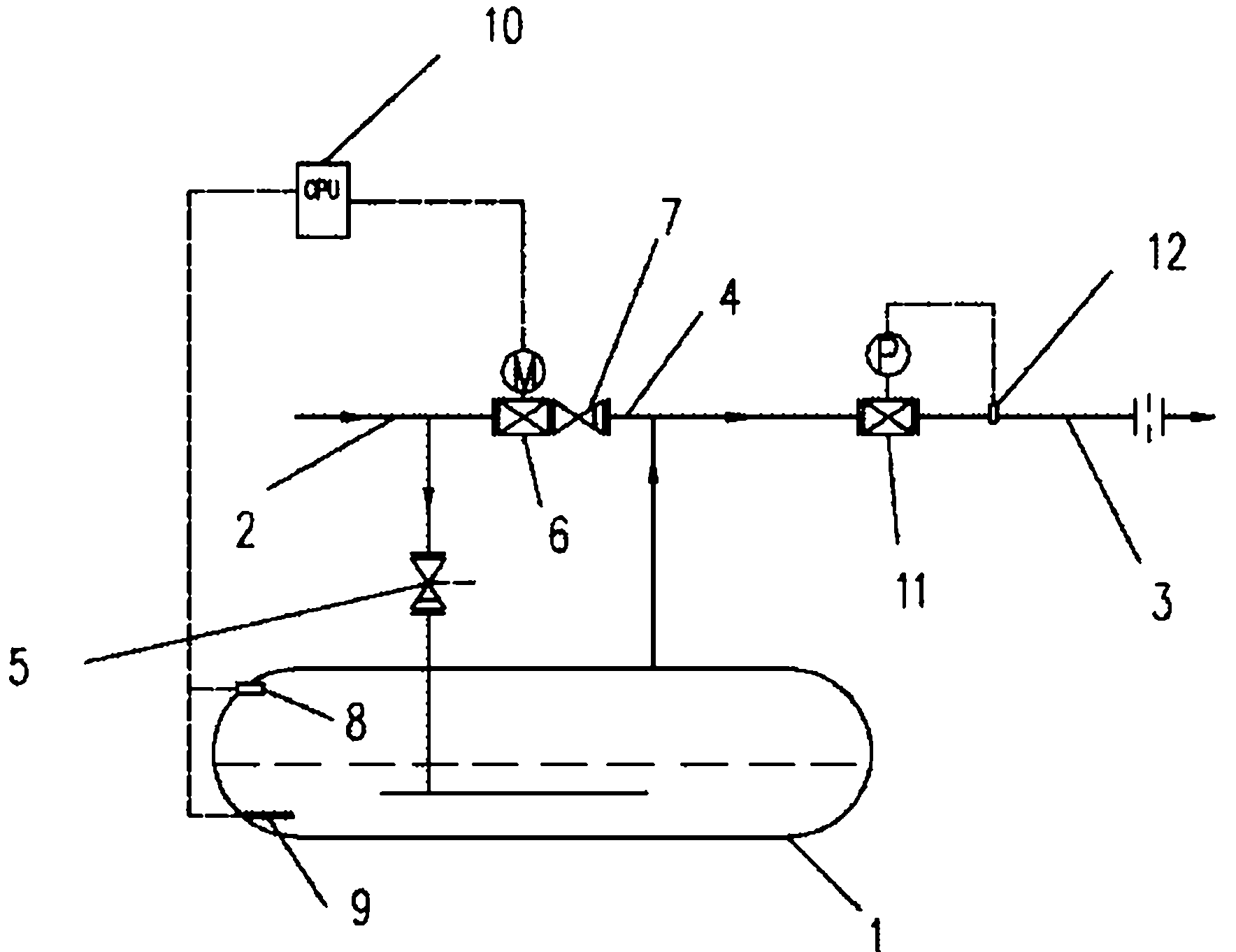
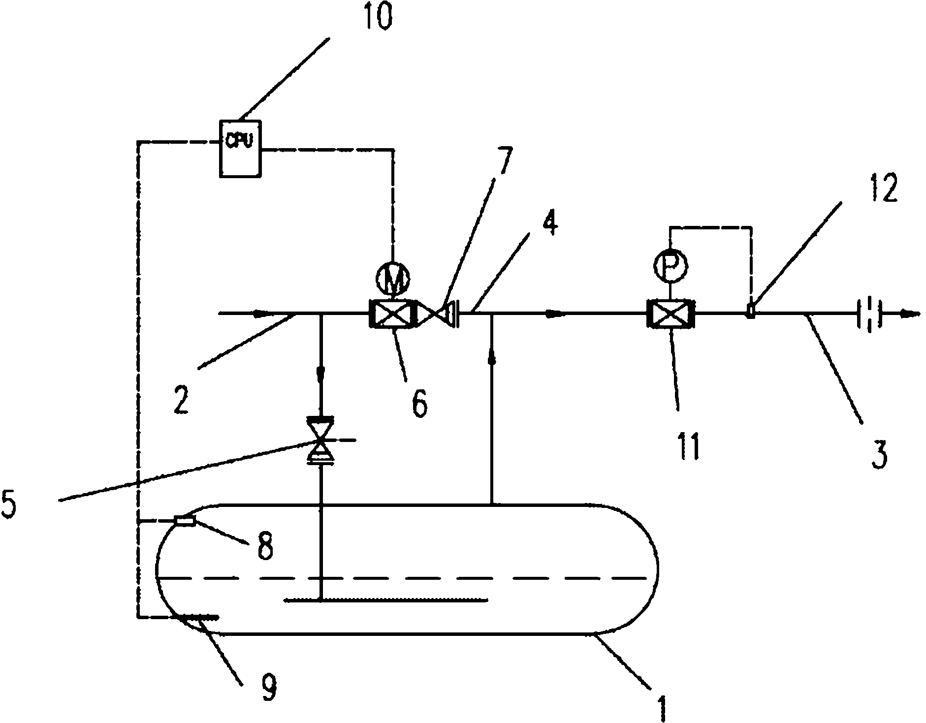
[0015] As shown in Figure 1, the temperature-controlled variable pressure heat accumulator control system described in this embodiment mainly includes a heat accumulator 1, and the heat accumulator 1 is connected with a steam inlet pipeline 2 and a steam outlet pipeline 3 respectively. A short-circuit pipe 4 is provided between the steam inlet pipe 2 and the steam outlet pipe 3 to communicate with each other, and an inlet check valve 5 is provided on the steam inlet pipe 2 between the short-circuit pipe 4 and the heat accumulator 1, and an inlet check valve 5 is provided on the short-circuit pipe 4. 4 is provided with a temperature control regulating valve 6 and a short-circuit check valve 7, and a steam pressure sensor 8 for measuring the saturated steam pressure and a water temperature sensor 9 for measuring the water temperature are also provided in the heat accumulator 1. The steam pressure sensor 8. The sensing signal of the water temperature sensor 9 is input to the contr...


PUM


Abstract

The invention discloses a temperature-control variable-pressure heat accumulator control system, which mainly comprises a heat accumulator. The heat accumulator is respectively communicated with a steam inlet pipe and a steam outlet pipe. A short loop pipe is arranged between the steam inlet pipe and the steam outlet pipe and communicates the steam inlet pipe with the steam outlet pipe. An inlet check valve is arranged on the steam inlet pipe between the short loop pipe and the heat accumulator. A temperature-control regulating valve and a short loop check valve are arranged on the short loop pipe. A steam pressure sensor and a water temperature sensor are arranged on the heat accumulator, wherein the steam pressure sensor is used for measuring saturated steam pressure and the water temperature sensor is used for measuring water temperature. The sensing signal of the steam pressure sensor and the sensing signal of the water temperature sensor are input to a controller. The output end of the controller is connected with the execution signal of the temperature-control regulating valve. A control method is characterized in that the temperature-control regulating valve is controlled through the deviation of the steam temperature and the water temperature to enable the inlet steam into two loops, wherein one loop is used for supplying steam and the other loop is used for accumulating heat and releasing heat if required. The invention has the advantages that the steam volume and the steam pressure are ensured to be stable and thereby the output of a waste heat recovery system is maintained to be maximum.

Description

technical field [0001] The invention relates to a heat storage device in the utilization process of waste heat steam, in particular to a control system and a control method for a temperature-controlled variable-pressure heat storage device. Background technique [0002] With the development of science and people's emphasis on energy saving and consumption reduction, the recovery and utilization of waste heat steam is more and more widely used in industry. For example, in order to save energy and recover waste heat in a steelmaking plant, a converter waste heat boiler is added. Since the steel production of the converter changes periodically, the waste heat of the flue gas discharged is intermittent and periodic, so that the converter waste heat boiler can only produce saturated steam intermittently, and The range of flow and pressure fluctuations is relatively large, which makes it difficult to effectively utilize steam, and almost all waste heat steam has the above phenomen...

Claims


Application Information

Patent Timeline
Patent Type & Authority Applications(China)
IPC IPC(8): F28D20/00
CPCY02E60/142Y02E60/14
Inventor 苟立刚赵振孙海云沈东
Owner ZHEJIANG XIZI UNITED ENG
Why Eureka
Try Eureka