

Permanent-magnetic drive speed adjustor
A technology of permanent magnet drive and governor, applied in the direction of asynchronous induction clutch/brake, etc., can solve the problems of electromagnetic interference, low efficiency, short life cycle, etc., and achieve the effect of reducing vibration
Active Publication Date: 2010-08-25
QINGDAO SPRING ENERGY TECH
View PDF4 Cites 13 Cited by
- Summary
- Abstract
- Description
- Claims
- Application Information
AI Technical Summary
Problems solved by technology
Although the hydraulic coupling can adjust the speed and save energy to a certain extent, its efficiency is low and it is not stable enough
Inverter and internal feedback chopper speed regulation are used to directly change the speed of the motor to adjust the system and load. The efficiency is high and the energy saving effect is good. The period is short and there is electromagnetic interference
Method used
View moreImage
Smart ImageViewing Examples

Examples
Embodiment Construction
Login to View More PUM
 Abstract
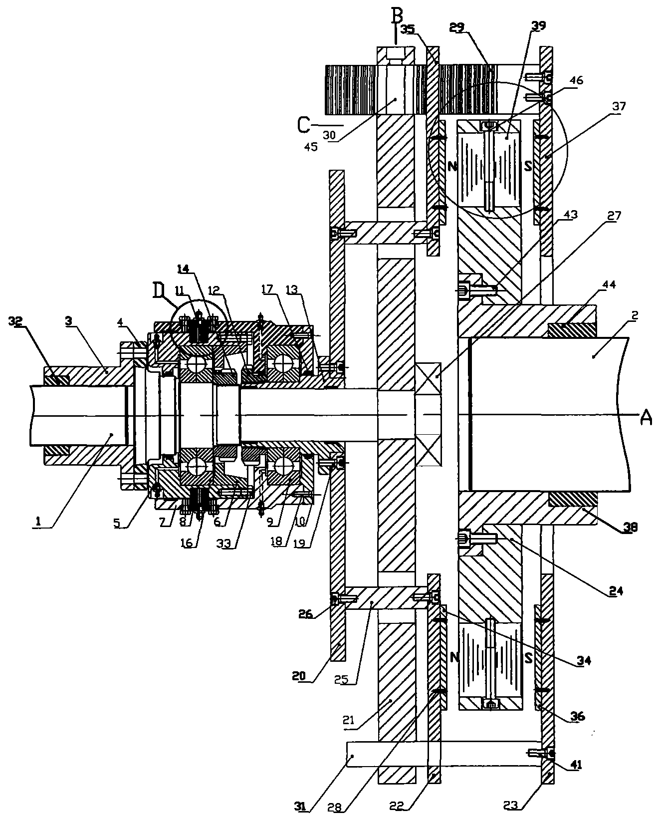
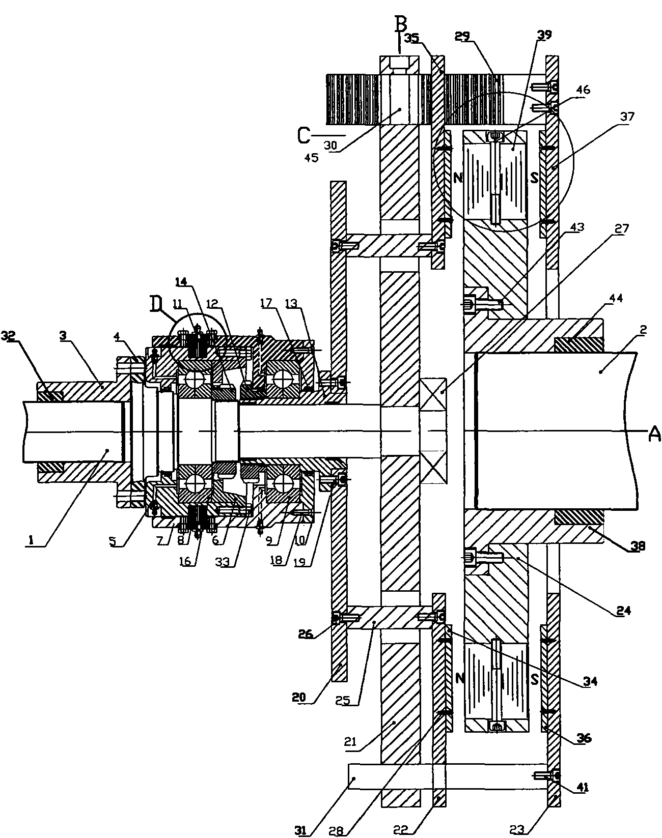
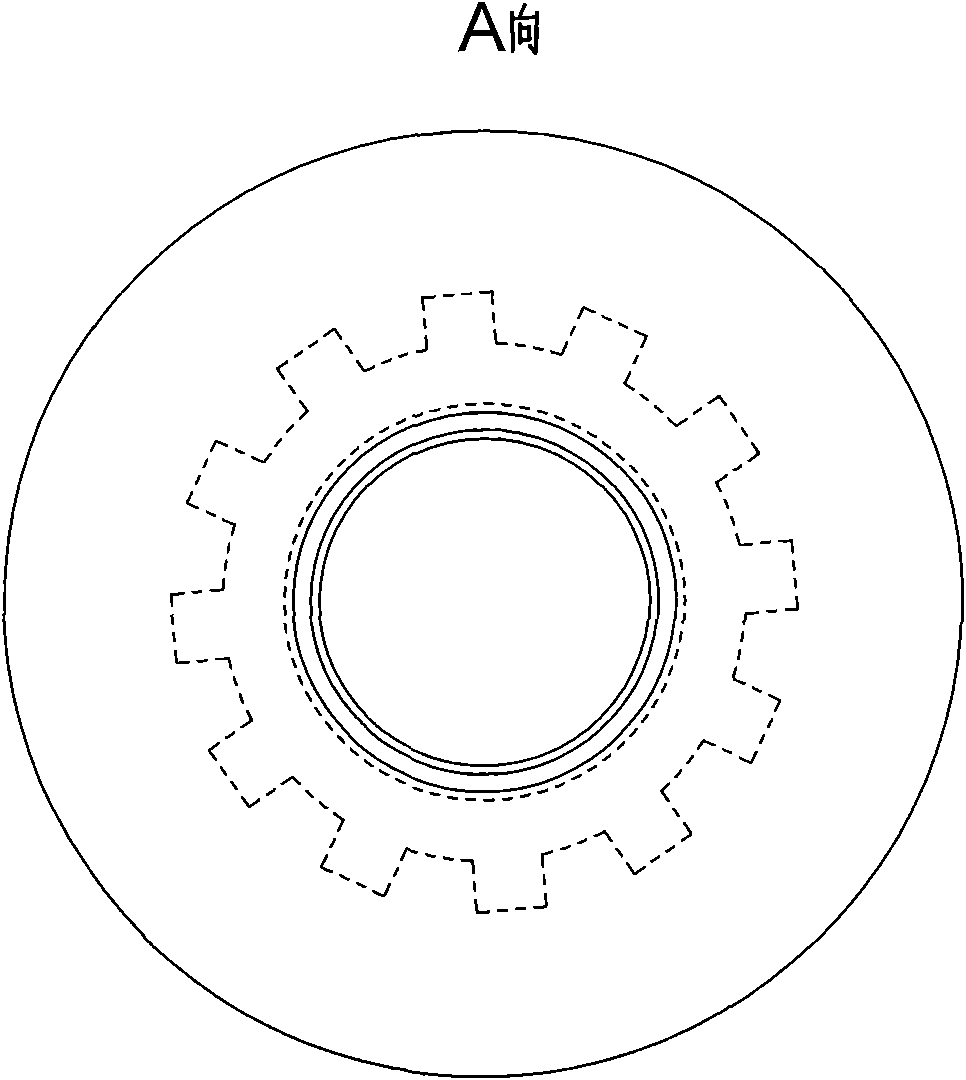
The invention provides a permanent-magnetic drive speed adjustor, which comprises a first shaft, a second shaft and an extension shaft, wherein the second shaft is connected with a permanent-magnetic turntable; the first shaft is connected with the extension shaft; the extension shaft is provided with a bearing, a shaft sleeve and an outer sleeve and connected with a cage-shaped rotor; the cage-shaped rotor consists of turntables, and two conductor discs are arranged on two sides of the permanent-magnetic turntable; the left small turntable is fixedly connected with the left conductor disc, the left second turntable is provided with a gear, and the two conductor discs are provided with a rack respectively; the right conductor disc is provided with a pin shaft which passes through the left conductor disc and penetrates the left second turntable; the conductor discs on two sides realize synchronous reverse equidistance motion through a gear and rack mechanism; and the first shaft and the second shaft can be connected with a motor or a load. The permanent-magnetic drive speed adjustor has the advantages of realizing non-contact power transfer of power, reducing vibration, starting the motor without load, changing the torque transferred between the conductor disc and the permanent-magnetic turntable, and repeatedly, adjustably and controllably outputting the torque and the rotational speed to fulfill the purposes of speed adjustment and energy conservation.
Description
A permanent magnet drive governor technical field The invention relates to a permanent magnet drive speed regulator, in particular to a drive speed regulator based on the principle of permanent magnet eddy current induction. Background technique Existing motor systems, especially centrifugal equipment systems, mainly use the following methods to regulate flow and pressure: damper baffles, valves, hydraulic couplings, frequency converters, and internal feedback chopper speed regulation. Dampers and valves are traditional methods, which can effectively adjust the flow or pressure, but the disadvantages are also obvious: they are not energy-saving, and they are easy to cause shocks in the system. Although the hydraulic coupling can adjust the speed and save energy to a certain extent, its efficiency is low and it is not stable enough. Inverter and internal feedback chopper speed regulation are used to directly change the speed of the motor to adjust the system and load. The ...
Claims
Login to View More Application Information
Patent Timeline
 Patent Type & AuthorityApplications(China)
IPC IPC(8): H02K49/04
Inventor王荣松
OwnerQINGDAO SPRING ENERGY TECH