
Intelligent air-cooled hydraulic punching and shearing machine

A punching and shearing machine and air-cooling technology, which is applied in the direction of shearing devices, shearing machine equipment, metal processing machinery parts, etc., can solve problems such as the temperature rise of hydraulic oil, achieve the effect of ensuring stable operation and improving cooling effect

Inactive Publication Date: 2010-09-01
丁健
View PDF2 Cites 2 Cited by
  • Summary
  • Abstract
  • Description
  • Claims
  • Application Information

AI Technical Summary

Problems solved by technology

[0003] The purpose of the present invention is to overcome the deficiencies of the prior art and provide an intelligent air-cooled hydraulic punching and shearing machine. An intelligent air-cooling device is installed on the oil return pipeline of the hydraulic system to solve the problem of the temperature rise of the hydraulic oil caused by the long-time work of the punching and shearing machine. problems, while adopting intelligent control to achieve the purpose of saving energy and reducing consumption

Method used


Image

  • Intelligent air-cooled hydraulic punching and shearing machine
  • Intelligent air-cooled hydraulic punching and shearing machine
  • Intelligent air-cooled hydraulic punching and shearing machine

Examples


Embodiment Construction

[0018] The following examples are used to illustrate the present invention, but are not intended to limit the scope of the present invention. All equivalent technical solutions also belong to the scope of the present invention, and the patent protection scope of the present invention should be limited by the claims.

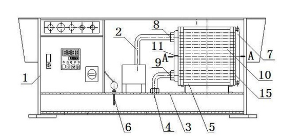
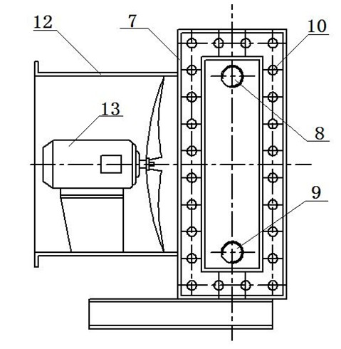
[0019] from figure 1 and figure 2 It can be seen from the above that an intelligent air-cooled hydraulic punching and shearing machine includes a frame 1, an oil return pipe 2 and an oil tank 3, the oil tank 3 is welded on the frame 1, and the oil tank 3 is provided with an oil return The port 4 is characterized in that an air cooling device 5 is arranged between the oil return pipe 2 and the oil return port 4 .

[0020] A temperature controller 6 is provided on the fuel tank 3 , and the temperature controller 6 controls the opening and closing of the air cooling device 5 .

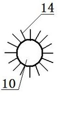
[0021] The air cooling device 5 includes a casing 7, an oil inlet 8 and an oil outlet...


PUM


Abstract

The invention discloses an intelligent air-cooled hydraulic punching and shearing machine. The machine comprises a machine frame, an oil return pipe and an oil tank, wherein the oil tank is welded on the machine frame; an oil return port is formed on the oil tank; and an air cooling device is arranged between the oil return pipe and the oil return port; the air cooling device comprises a shell; the shell is provided with an oil inlet and an oil outlet respectively; uniformly-distributed radiating pipes are welded at the two ends of the shell through partition boards; a channel of hydraulic oil is formed by an oil partition board of the shell; the channel is connected with the oil inlet and the oil outlet of the shell respectively; the oil inlet is connected with the oil return pipe; and the oil outlet is connected with the oil return port. The temperature of the hydraulic oil in the oil return pipe is reduced by the air cooling device so that the increase of the oil temperature can be effectively controlled, the stable operation of the machine is ensured and energy is saved.

Description

technical field [0001] The invention relates to a hydraulic punching and shearing machine, in particular to a cooling technology of hydraulic oil used in the hydraulic punching and shearing machine. Background technique [0002] With the rapid development of the machinery industry, the punching and shearing machine has developed from the original mechanical transmission to the hydraulic transmission. The hydraulic punching and shearing machine cannot be separated from the hydraulic transmission. The temperature of the oil in the hydraulic transmission is generally controlled in the range of 60℃~80℃. The maximum should not exceed 85 ℃. If the oil temperature is too high, the hydraulic system will have adverse effects. After the oil temperature rises, the viscosity of the oil decreases, the cohesion of the oil decreases, the leakage increases, the machine running speed is unstable, and crawling is easy to occur: after the oil temperature rises, the pressure of the hydraulic s...

Claims


Application Information

Patent Timeline
IPC IPC(8): B23Q11/12B23D27/06
Inventor 丁健
Owner 丁健
Learn More