Flow transmitter provided with double differential pressure sensors and pressure difference measurement method

A flow transmitter and sensor technology, which is applied in the direction of measuring fluid flow by measuring differential pressure, volume/mass flow generated by mechanical effects, etc., can solve problems such as complexity, high cost, and the inability of low-pressure differential sensors to withstand high pressure differential, and achieve The effect of widening the measurement range and overcoming technical difficulties

Inactive Publication Date: 2010-09-01
无锡求信流量仪表有限公司
View PDF8 Cites 16 Cited by
  • Summary
  • Abstract
  • Description
  • Claims
  • Application Information

AI Technical Summary

Problems solved by technology

However, the existing differential pressure flowmeter cannot meet the wide-range measurement requirements; if two differential pressure sensors are used, a high-pressure differential sensor is used for large flow rates and a low-pressure differential sensor is used for small flow rates, of course the range can be greatly expanded, but the low differential pressure The sensor cannot withstand the high pressure difference condition, so two sensors can only be installed on two pipes, and then use the automatic control scheme to use the pipe with the large pressure difference sensor when the flow is large, and install the low pressure difference sensor when the flow is small pipeline
This is an expensive and complicated project

Method used


Image

  • Flow transmitter provided with double differential pressure sensors and pressure difference measurement method
  • Flow transmitter provided with double differential pressure sensors and pressure difference measurement method
  • Flow transmitter provided with double differential pressure sensors and pressure difference measurement method

Examples


Embodiment 1

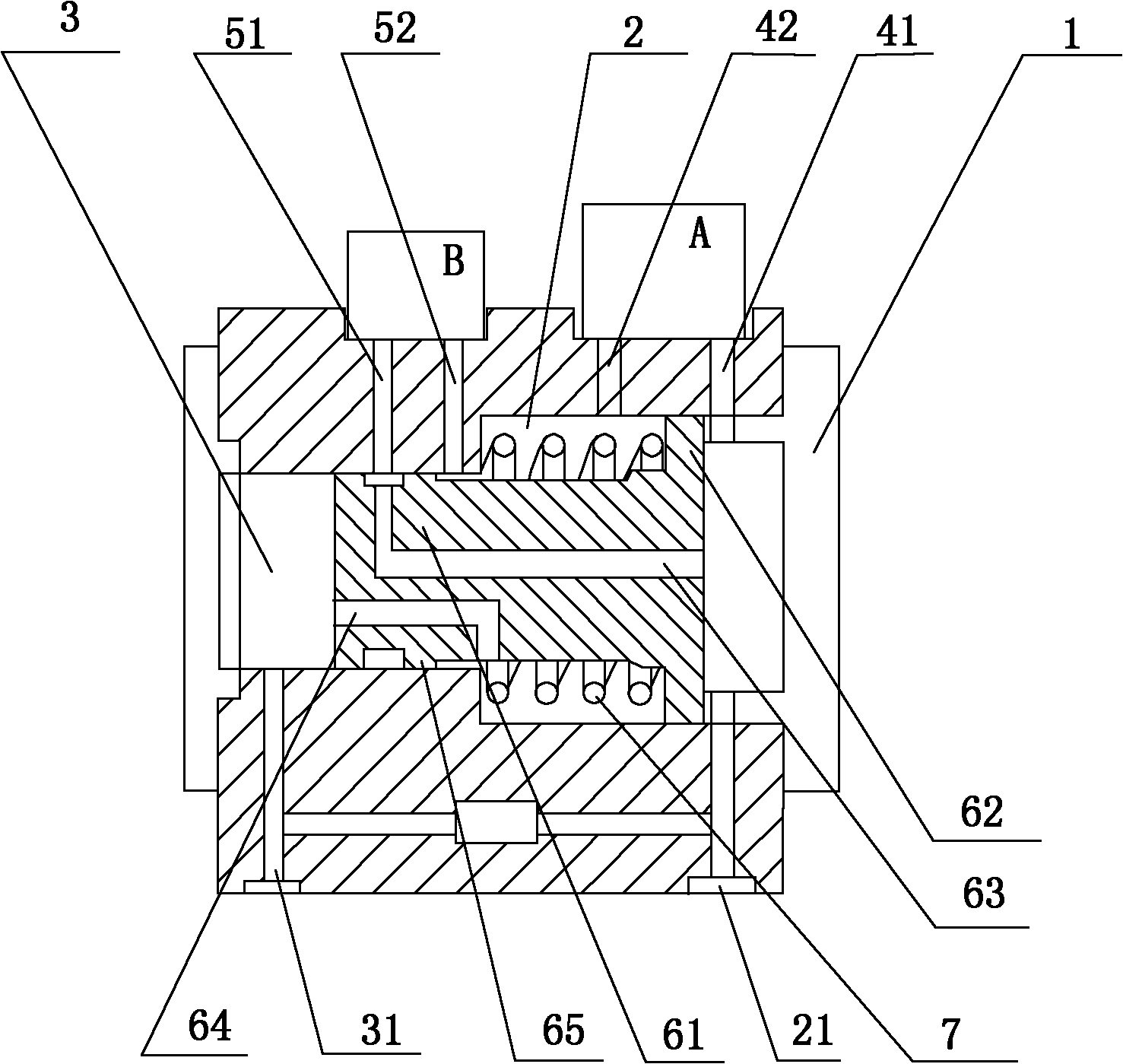
[0025] Embodiment 1: as figure 1 , the end side of the cylinder 61 of the piston 6 is in a sealed state with the inner wall of the small cavity 3, the rest of the cylinder 61 is not sealed, and the elastic component 7 is a spring. When the spring is not compressed, that is, when the piston 6 is not moving, corresponding to the positions of the two low-pressure differential measurement module (B) measuring holes 51 and 52 on the small chamber 3, an annular sealing step 65 is provided on the cylinder 61, and the barrier height Low-pressure measuring holes 51, 52. The piston 6 is provided with a high-pressure communication hole 63 and a low-pressure communication hole 64. The high-pressure communication hole 63 is connected to the high-pressure side of the large chamber 2 and the high-pressure measuring hole 51 of the low-pressure differential measurement module (B); the low-pressure communication hole 64 is connected to the piston rod of the small chamber 3. The outside of the ...

Embodiment 2

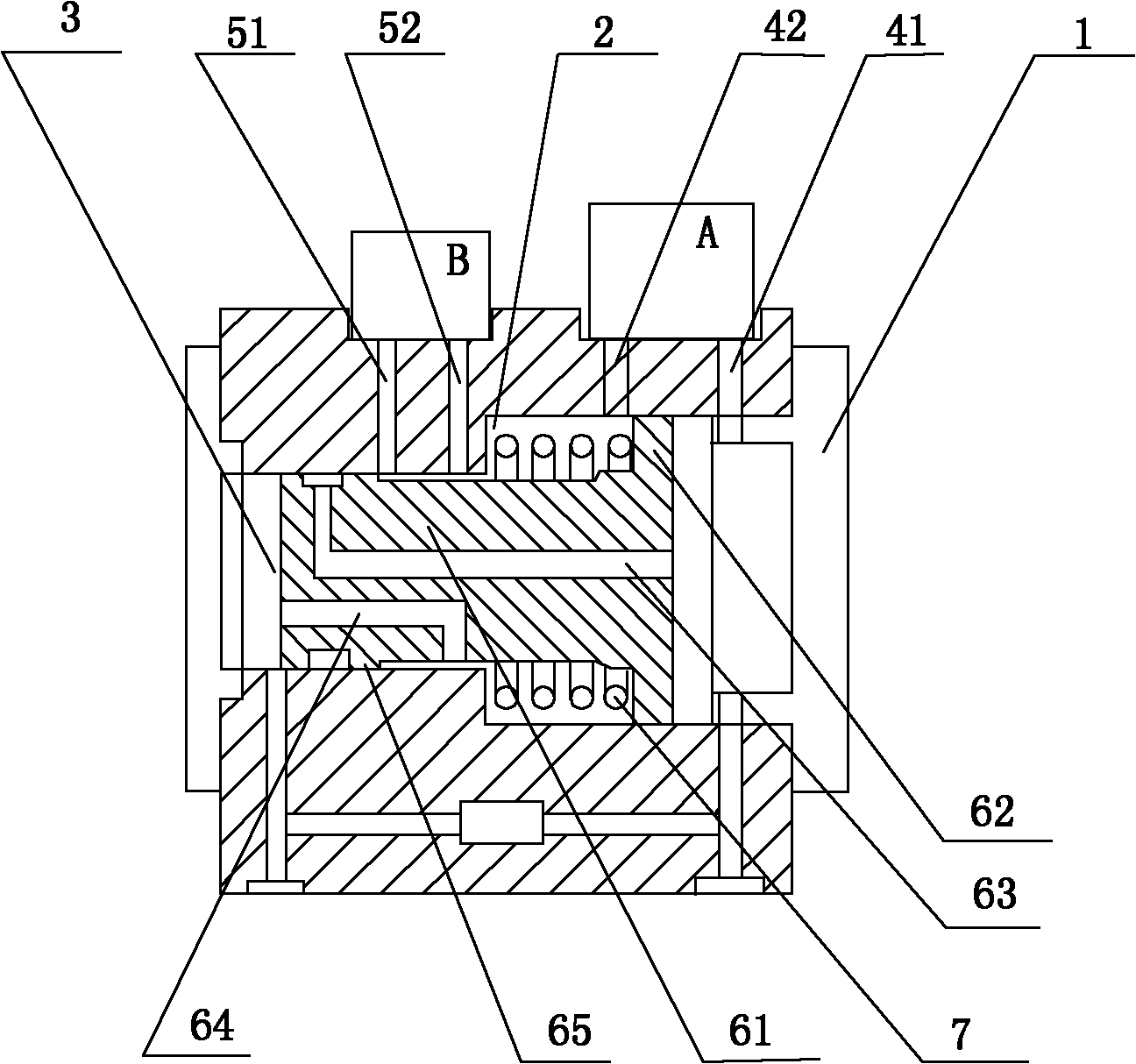
[0029] Example 2: image 3 As shown, the low-pressure measuring hole 42 of the high-pressure differential measurement module (A) is connected to the outside of the cylinder 61 of the small cavity 3; The inner wall is divided into two holes, one is connected to the high pressure measuring hole 41 of the high pressure difference measurement module (A) through the groove 66 on the surface of the cylinder and the high pressure communication hole 63 opened on the shell shell, and the other is blocked by the sealing step 65 . A low-pressure communication hole 64 is opened on the cylinder 61 .

[0030] Figure 4 After the piston 6 moves, the sealing step 65 blocks the passage between the original high-pressure measuring hole 51 and the high-pressure communication hole 6, and opens the connection between the high-pressure measuring hole 51 and the low-pressure side of the large chamber 2. At this time, the low-pressure differential measurement module (B) Both the high and low press...

Embodiment 3

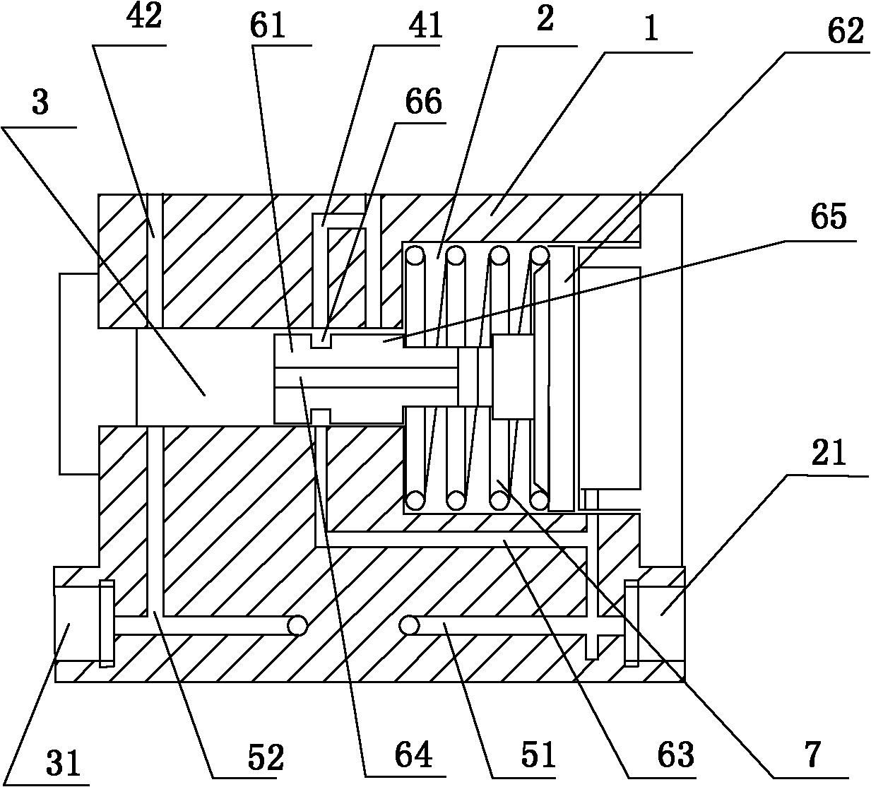
[0031] Example 3: Figure 5, the cylinder 62 is in sealing fit with the inner wall of the small cavity 3, and an annular groove is formed on the cylinder 62, and the high-pressure communication hole 63 is communicated with the high-voltage measuring hole 51 of the low-pressure differential measurement module (B) through the annular groove; the low-pressure communication hole 64 It communicates with the low-pressure measuring hole 42 of the high-pressure differential module (A), and is sealed by the cylinder 62 when the elastic component 7 is not working. At this time, the high-pressure measuring hole 51 of the low-pressure differential measurement module (B) bears the high pressure from the outside of the piston head flange 62 introduced from the high-pressure communication hole 63 and coming through the annular groove.

[0032] Figure 6 , the pressure difference is too large, the elastic component 7 is compressed to the dead point position, and the annular groove connects t...


PUM


Abstract

The invention discloses a differential pressure type flow transmitter provided with two differential pressure sensors. The flow transmitter is characterized in that a piston consisting of a cylinder and a head flange is arranged in an outer shell; a big cavity is partitioned into high and low pressure regions by the head flange of the piston; the piston is provided with an elastic component; the outer shell is provided with measurement holes of a high pressure difference measurement module (A) and a low pressure difference measurement module (B); high and low pressure measurement holes of thehigh pressure difference measurement module (A) ensure that two dead centre positions for compression and ejection of the elastic component are positioned in high and low pressure regions respectively; when the elastic component is not compressed, the high pressure measurement hole of the low pressure difference measurement module (B) is connected with the high pressure region; the elastic component is compressed to the dead centre position, the piston is moved to the end and the connecting channel is cut off. The transmitter can automatically switch the working channel of the low pressure difference measurement module (B) according to the pressure difference size so as to change the operating state of the low pressure difference measurement module (B) and protect the low pressure difference module; and meanwhile, the measurement range can be expanded by effectively using two pressure difference measurement modules.

Description

technical field [0001] The invention relates to a flow measuring device, in particular to a flow transmitter using high and low double pressure difference sensors. Background technique [0002] The differential pressure flowmeter ranks first in the list of flowmeters due to its mature technology, simple structure, stability and reliability, and wide application range. However, the fundamental problem with this type of differential pressure flowmeter is the narrow measurement range. Because the flow rate has a square function relationship with the pressure difference, if the flow rate is 100 times the minimum value, then the pressure difference is 10,000 times the minimum value, which limits the measurement range. Usually 1:4 or 1:10 is already great now. According to the publication of the self-adaptive differential pressure flowmeter in "Flowmeter Information Network", it is said that it can achieve 1:20. However, in actual engineering, the required flow range is often r...

Claims


Application Information

Patent Timeline
Patent Type & Authority Applications(China)
IPC IPC(8): G01F1/34G01F1/38
Inventor 徐蠡徐孟飚
Owner 无锡求信流量仪表有限公司
Why Eureka
Try Eureka