Device for monitoring state and diagnosing fault of power electronic circuit

A technology of power electronic circuit and fault diagnosis device, which is applied in the field of power electronic circuit, and can solve problems such as large current, non-isolated detection circuit, and high voltage

Inactive Publication Date: 2010-09-01
HUAZHONG UNIV OF SCI & TECH
View PDF0 Cites 23 Cited by
  • Summary
  • Abstract
  • Description
  • Claims
  • Application Information

AI Technical Summary

Problems solved by technology

[0005] ① Due to the need for measuring components such as voltage and current transformers and Hall, and the detection components have parasitic parameters, the detection circuit cannot actually be completely isolated from the main circuit, the electromagnetic interference is large, and the diagnosis may be biased;
[0006] ②For medium and high voltage large-capacity converters, the voltage is high and the current is large, which requires large voltage and current transformers, and the cost is high;

Method used


Image

  • Device for monitoring state and diagnosing fault of power electronic circuit
  • Device for monitoring state and diagnosing fault of power electronic circuit
  • Device for monitoring state and diagnosing fault of power electronic circuit

Examples


Embodiment

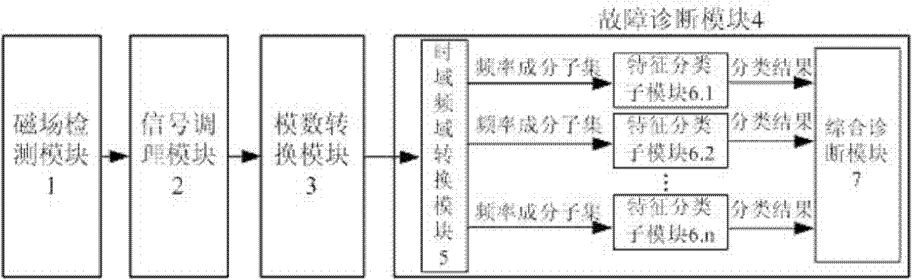
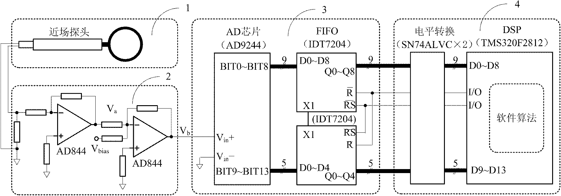
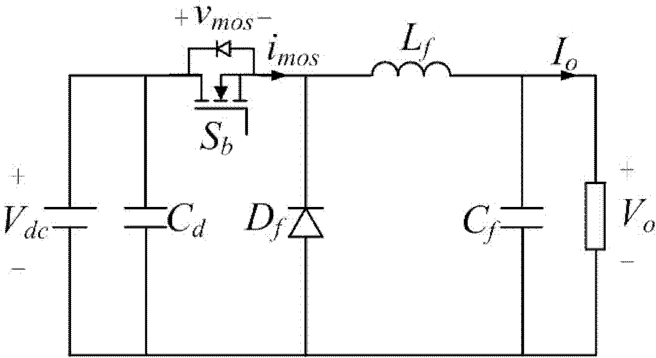
[0041] Below in conjunction with accompanying drawing and example the present invention is described in further detail. figure 2 It is a schematic diagram of a specific state monitoring and diagnosis device designed for a BUCK circuit based on the idea of ​​the present invention. The schematic diagram of the BUCK circuit is shown in image 3 shown. The rated index of the BUCK circuit is: the switching frequency is 24KHz, the rated input voltage is 50V, the rated output voltage is 30V, and the rated current is 2A. The specific implementation of each module is as follows:

[0042] Magnetic field detection module 1: According to the characteristics of the magnetic field radiation of the BUCK circuit, the magnetic field measurement element is selected from the LF-R 400 probe provided by the company. The probe is placed at the filter inductance (Lf) air gap of the BUCK circuit in order to obtain a significant magnetic field signal. A typical waveform detected by the probe is ...


PUM


Abstract

The invention discloses a device for monitoring the state and diagnosing the fault of a power electronic circuit. The device has a structure that: a magnetic field detection module detects the magnetic field strength of the power electronic circuit, a signal conditioning module amplifies a voltage signal and an analog-to-digital conversion module performs analog-to-digital conversion; a fault diagnosis module comprises a time-domain and frequency-domain conversion module, a characteristic sort module and a comprehensive diagnosis module; the time-domain and frequency-domain conversion module is used for extracting the frequency characteristics of a time-domain waveform and supplies the frequency characteristics to characteristic sort sub-modules respectively; the characteristic sort sub-modules compare the received subsets to obtain partial diagnosis results corresponding to each characteristic subset and supply the results to the comprehensive diagnosis module; and the comprehensive diagnosis module synthesizes the partial diagnosis results of each characteristic subset to obtain a final diagnosis result. The device realizes the natural isolation of a detector from a main circuit; the different kinds of information carried by the magnetic field signal are treated respectively and then comprehensively judged, so the accuracy is higher; and the device can be applied to various power electronic circuits.

Description

technical field [0001] The invention relates to a power electronic circuit technology, in particular to a state monitoring and fault diagnosis device for a power electronic circuit, which is a non-contact state monitoring and fault diagnosis device for a power electronic circuit based on magnetic field near-field radiation. Background technique [0002] With the rapid development of power electronic technology, power electronic products represented by switching power supply, UPS power supply and variable frequency power supply have been widely used in all walks of life, and their normal operation is crucial to ensuring the safety of power systems and industrial production processes , high-efficiency, and high-quality operation are very important, so its reliability, fault diagnosis and function reconstruction technology, and electromagnetic compatibility are all topics that must be studied. Fault diagnosis of power electronic circuits can detect abnormalities in the circuit ...

Claims


Application Information

Patent Timeline
Patent Type & Authority Applications(China)
IPC IPC(8): G01R31/302G01R33/02
Inventor 裴雪军陈宇聂松松康勇
Owner HUAZHONG UNIV OF SCI & TECH
Why Eureka
Try Eureka