Driving device of light-emitting element

A technology for driving devices and light-emitting diodes, applied in lighting devices, light sources, electric light sources, etc., can solve problems such as short charge pump time

Active Publication Date: 2010-09-01
SHANGHAI AWINIC TECH CO LTD
View PDF4 Cites 5 Cited by
  • Summary
  • Abstract
  • Description
  • Claims
  • Application Information

AI Technical Summary

Problems solved by technology

[0005] The present invention solves the technical problem that the charge pump works in the 1-fold working mode for a shorter time in the prior art

Method used


Image

  • Driving device of light-emitting element
  • Driving device of light-emitting element
  • Driving device of light-emitting element

Examples


Embodiment Construction

[0022] The specific embodiments of the present invention will be described in detail below in conjunction with the accompanying drawings. In the following paragraphs the invention is described more specifically by way of example with reference to the accompanying drawings. Advantages and features of the present invention will become apparent from the following description and claims.

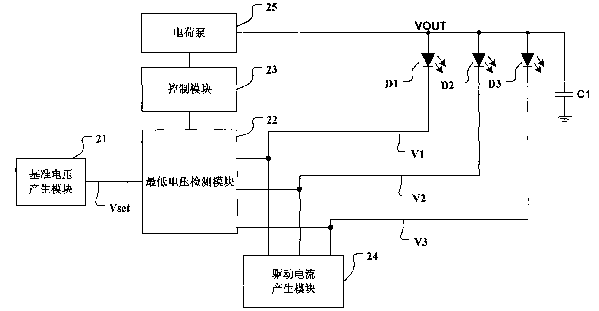
[0023] The present invention provides a driving system for a light-emitting element, and the following embodiments only use the light-emitting diode group including three LED light sources as an example for illustration.

[0024] Such as figure 1 As shown, a driving system for a light-emitting element includes: a reference voltage generation module 21, a minimum voltage detection module 22, a control module 23, a driving current generation module 24, and a charge pump 25. The first LED light source D1 and the second LED light source D2, a light emitting diode group composed of the third LED li...


PUM


Abstract

The invention provides a driving device of a light-emitting element, comprising a reference voltage generating module, a minimum voltage detecting module, a control module and a driving control current generating module, wherein the reference voltage generating module is used for supplying reference voltage for the minimum voltage detecting module; the minimum voltage detecting module is used for detecting the cathode voltage of each light-emitting diode in a light-emitting diode set and then generating switching signals when the minimum in each cathode voltage is less than the generating value of the reference voltage; when receiving the switching signals, the control module controls a charge pump so that the charge pump adjusts anode voltages outputted to the light-emitting diode set; and the driving control current generating module is used for supplying constant current for the light-emitting diode set when the minimum of the cathode voltages is not less than the reference voltage. Compared with the prior art, the invention obtains the minimum of the cathode voltages of the conducted light-emitting diodes to accurately control the output voltage of the charge pump through detecting the cathode voltages of all light-emitting diodes so that the charge pump works under the initial working mode in a longer time than that of the prior art.

Description

technical field [0001] The invention relates to a driving device for a light emitting element. Background technique [0002] Handheld devices such as mobile phones and MP3s basically use color liquid crystal displays, and white light emitting diodes (Light Emitting Diode, LED) are used as a general backlight source. For example, Chinese patent application number 200520067489.0 discloses a backlight control circuit. However, due to the deviation of the LED production process, the conduction voltage drop required for the same current to flow through different LEDs will be different. At present, the mainstream white light LED flows a current of 20mA, and the deviation of the conduction voltage drop is 0.2V. [0003] Usually, a handheld device uses a lithium-ion battery to power the entire backlight and its drive system. The rated voltage of the lithium battery is 3.6V, and it is 4.2V when fully charged. When the handheld device is working, the lithium battery is continuously ...

Claims


Application Information

Patent Timeline
Patent Type & Authority Applications(China)
IPC IPC(8): H05B37/02
CPCY02B20/42Y02B20/40
Inventor 余维学史亚军王朝管来东孙洪军
Owner SHANGHAI AWINIC TECH CO LTD
Why Eureka
Try Eureka