Contact clip

A technology of contact clips and contact pieces, which is applied in the direction of connections, parts of connecting devices, electrical components, etc., and can solve problems such as large contact resistance.

Active Publication Date: 2010-09-01
PRECI DIP
View PDF1 Cites 10 Cited by
  • Summary
  • Abstract
  • Description
  • Claims
  • Application Information

AI Technical Summary

Problems solved by technology

A disadvantage of the contact clip as described in this document is that when the male contact is introduced, the contact clip has a relatively limited contact surface with the male contact, which

Method used


Image

  • Contact clip
  • Contact clip
  • Contact clip

Examples


Embodiment Construction

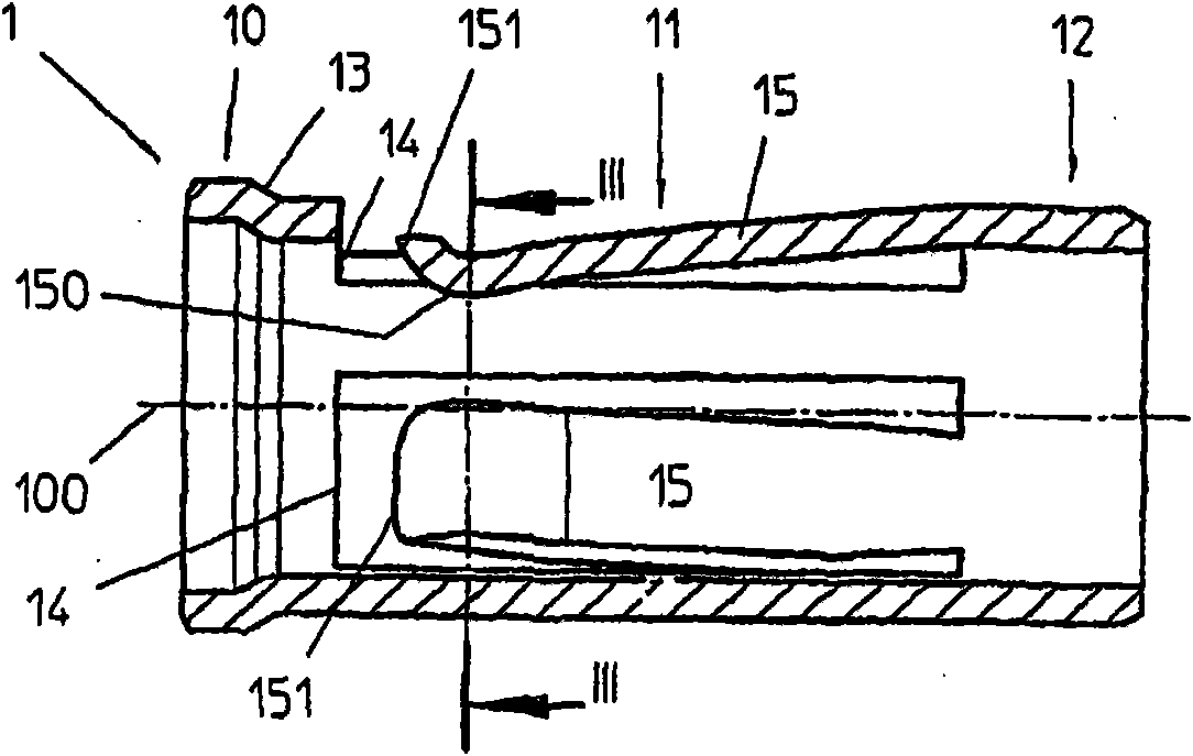
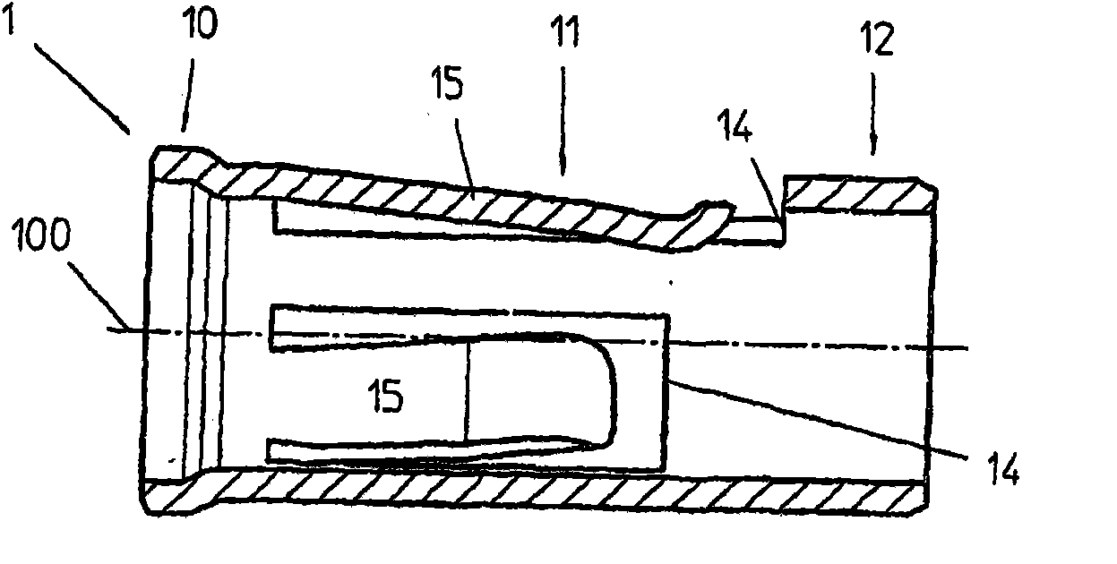
[0015] as in figure 1 The contact clip 1 shown in figure 1 In the embodiment, it includes a fixed part 10, a contact part 11 and an end part 12 from left to right along its length direction.

[0016] As will be seen below, the fixing part 10 consists of a cylindrical ring-shaped part for fixing the contact clip 1 in the corresponding part of the contact. Therefore, the largest dimension of this fixed part 10 is its outer diameter. To fix the fixing part 10 in the contact, in the embodiment shown, requires that the outer diameter of said fixing part is larger than that of the other parts, the frustoconical part 13 being able to engage these diameters.

[0017] In the embodiment shown, the end portion 12 arranged at the opposite end of the contact clip consists of a cylindrical tubular portion intended to be inserted into a corresponding contact piece as will be seen below. in the boot section. For the part 12, its largest dimension is also its outer diameter.

[0018] The ...


PUM


Abstract

The contact clip according to the invention comprises a contact portion (11) comprising two elastic blades (15) capable of pressing a male contact portion (2) against an interior cylindrical portion (110) of the said contact portion. In view of the elongate shape of this contact portion, electrical contact between the contact clip and the male contact piece portion is had over a large surface area, thus reducing the contact resistance and the heating when high currents are passed. The contact clip further comprises an attachment portion (10) and possibly an end portion (12) and is intended to be fitted inside a hollow housing of a female contact piece (3).

Description

technical field [0001] The invention relates to a contact clip intended to be introduced inside a female contact to complete this contact, said contact clip being able to ensure an electrical connection between said female contact and a corresponding male contact. The invention also relates to a contact piece equipped with such a contact clip and a connector to which at least one such contact piece is mounted. Background technique [0002] Application EP-1107378 describes a female contact piece fitted with a contact clip, intended to be arranged on a multi-contact connector. A disadvantage of the contact clip as described in this document is that when the male contact is introduced, the contact clip has a relatively limited contact surface with the male contact, which means that the contact resistance is relatively large, thus limiting the possible The value of the current delivered by such a set of contacts to avoid prohibitive heating of the set of contacts. [0003] A f...

Claims


Application Information

Patent Timeline
IPC IPC(8): H01R13/187
CPCH01R13/111H01R13/187
Inventor G·汉高特纳P·莱曼
Owner PRECI DIP
Why Eureka
Try Eureka