A cooling device for anti-meshing of bearing rings after forging

A technology of a bearing ring and a cooling device, applied in the field of cooling devices, can solve problems such as unfavorable production, time-consuming site storage, easy wear and tear of conveyor belts, etc., achieving the effects of strong automation, reducing energy consumption, and avoiding uneven cooling

Active Publication Date: 2018-01-23
FUJIAN YONGAN BEARING
View PDF6 Cites 0 Cited by
  • Summary
  • Abstract
  • Description
  • Claims
  • Application Information

AI Technical Summary

Problems solved by technology

Due to the difference in temperature between the bearing rings, heat transfer will occur between the bearing rings, causing the temperature of a single bearing ring to rise and fall repeatedly, which is extremely unfavorable for the transformation and formation of its internal structure, and it is easy to produce reticular carbides, etc. defect
2. Spread the bearing rings on the ground, although it can avoid the heat transfer between the bearing rings, but for mass production manufacturers, this not only requires a large area to install cooling nozzles, but also requires a lot of cost. The large area of ​​the site and the large amount of retracting time are neither conducive to production nor practical
Due to the high temperature of the bearing rings, the above-mentioned conveyor belt must be composed of iron or / and steel roller chains in actual production, which makes the conveyor belt heavy, resulting in high power requirements for equipment and high energy consumption, and this conveyor belt is easy to Wear and rust, requiring frequent maintenance or replacement; in addition, the cooling device cannot accurately control the cooling temperature of the bearing ring, which may easily cause reticular carbides to appear inside the bearing ring, affecting the performance of the bearing ring

Method used


Image

  • A cooling device for anti-meshing of bearing rings after forging
  • A cooling device for anti-meshing of bearing rings after forging
  • A cooling device for anti-meshing of bearing rings after forging

Examples


Embodiment Construction

[0028] Specific embodiments of the present invention will be described below with reference to the accompanying drawings.

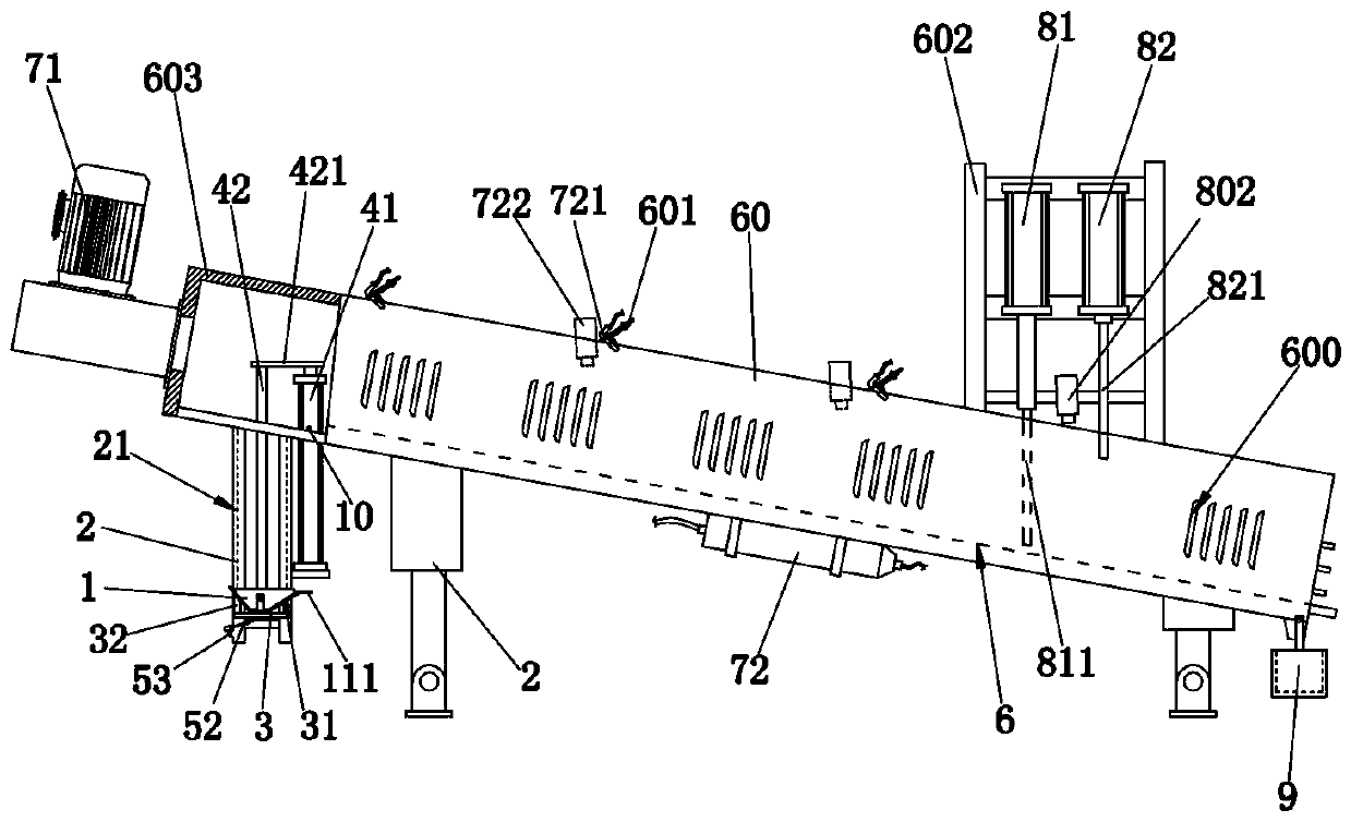
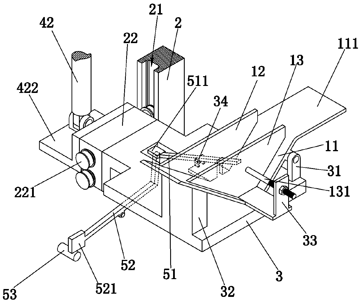
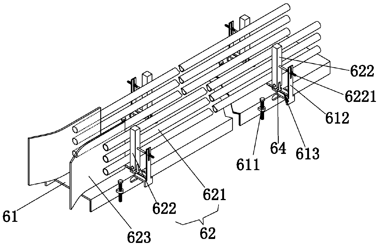
[0029] refer to figure 1 and Figure 4 , a cooling device for anti-meshed bearing rings after forging, including a frame 2, a feeding part, a cooling part and a discharging part. Wherein, the above-mentioned cooling part includes an atomizer 72 and a box body 60 . The box body 60 is arranged on the frame 2 obliquely in the left and right directions, and as a preferred solution: the box body 60 is arranged on the frame 2 so that the inclination can be adjusted. The box body 60 is provided with an inlet and an outlet, and a track 6 for the bearing ring a to roll is arranged inside the box body 60 . The box body 60 is provided with a plurality of nozzles 721 and first temperature sensors 722 arranged at intervals along the length direction of the track 6 directly above the track 6 . Each nozzle 721 communicates with the atomizer 72 and is equipped with a...


PUM


Abstract

The invention discloses a cooling device for anti-net of after-forge bearing ring, relating to cooling in process of production, including frame, material loading part, cooling part and discharging part; wherein cooling part includes nebulizer, box, track and a plurality of nozzles; Material loading part includes lifting platform, sliding mechanism and hopper; Discharging part includes the first cylinder and the second cylinder, and the piston rod of the first cylinder is provided with the first lever, and the piston rod of the second cylinder is provided with the second lever; Casing is obliquely installed in the frame, and material loading part is arranged just below the entrance of the box, and discharging part is arranged at the exit of the box. The chiller has the folling advantagea: it can carry out comprehensive cooling to after-forge bear rings of about 800oC , can accurately control the coolling temperature to meet the technical requirements, effectively preventing bearing rings from production defects such as net carbide; Inclined box can realize unpowered delivery of bear rings and thus reducing energy consumption.

Description

technical field [0001] The invention relates to the field of devices used for cooling during processing, in particular to a cooling device for preventing meshing of bearing rings after forging. Background technique [0002] The final forging temperature of the bearing ring after forging reaches about 850 ° C, and it is required to use an appropriate cooling method to cool it. If the cooling rate is too fast, cracking of the forging is likely to occur; if the cooling rate is too slow, defects such as network carbides are likely to precipitate along the grain boundaries, which will affect the performance of the bearing ring. [0003] The existing cooling methods for bearing rings include the following three methods: 1. Pile the forged bearing rings on the material frame or on the ground, and then cool them with cooling nozzles. Due to the difference in temperature between the bearing rings, heat transfer will occur between the bearing rings, causing the temperature of a singl...

Claims


Application Information

Patent Timeline
Patent Type & Authority Patents(China)
IPC IPC(8): B21K1/04B21K29/00
CPCB21K1/04B21K29/00
Inventor 章志慧卢健清陈正彬
Owner FUJIAN YONGAN BEARING
Why Eureka
Try Eureka