Hybrid power heat dissipation device for outdoor power distribution cabinet based on centrifugal force principle

A hybrid power and heat dissipation device technology, applied in the field of electric power, can solve problems such as internal short circuit of power distribution cabinet, collision of power distribution cabinet, damage of electronic components, etc., so as to improve the effect of heat dissipation, ensure the effect of heat dissipation, and prevent uneven heat dissipation Effect

Active Publication Date: 2020-06-16
南京博普电气成套有限公司
View PDF9 Cites 2 Cited by
  • Summary
  • Abstract
  • Description
  • Claims
  • Application Information

AI Technical Summary

Problems solved by technology

[0003] There are various electronic components inside the power distribution cabinet, and the electronic components will generate heat when they work. Ordinary power distribution cabinets dissipate heat by setting up heat dissipation windows on the side walls of the cabinet. The heat dissipation effect is not good, which affects the stable operation of electronic components; The working environment of the power distribution cabinet is relatively more complicated. The ordinary power distribution cabinet has a single function and lacks corresponding protective measures. Rainwater can easily enter the interior of the power distribution cabinet through the heat dissipation window, which will cause damage to the electronic components inside the power distribution cabinet and cause power outages in some areas. , and even cause a natural short circuit inside the distribution cabinet, and the outdoor distribution cabinet is prone to collision, and the collision of the distribution cabinet may also cause

Method used


Image

  • Hybrid power heat dissipation device for outdoor power distribution cabinet based on centrifugal force principle
  • Hybrid power heat dissipation device for outdoor power distribution cabinet based on centrifugal force principle
  • Hybrid power heat dissipation device for outdoor power distribution cabinet based on centrifugal force principle

Examples


Embodiment Construction

[0029] The following will clearly and completely describe the technical solutions in the embodiments of the present invention with reference to the accompanying drawings in the embodiments of the present invention. Obviously, the described embodiments are only some, not all, embodiments of the present invention. Based on the embodiments of the present invention, all other embodiments obtained by persons of ordinary skill in the art without making creative efforts belong to the protection scope of the present invention.

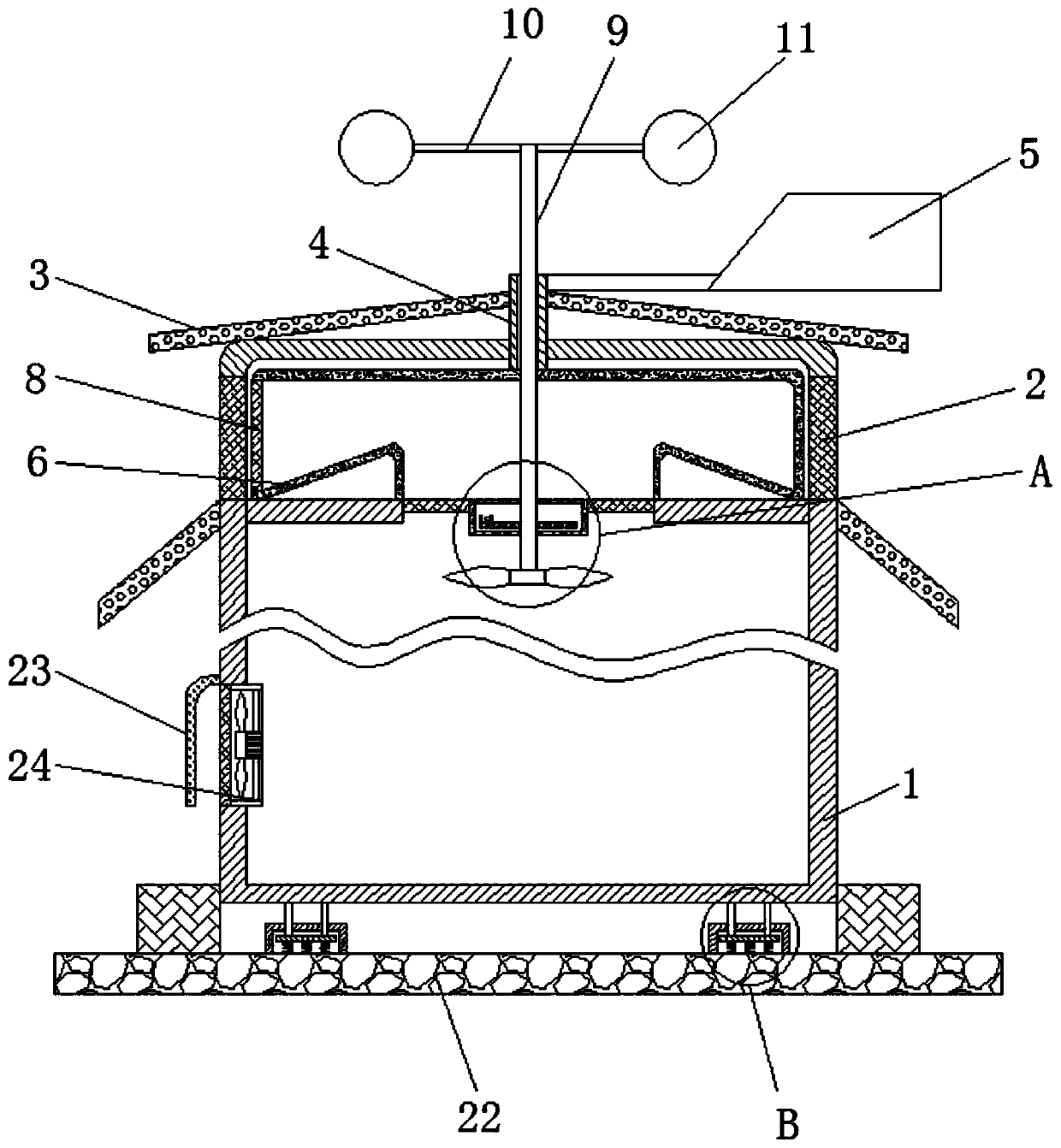
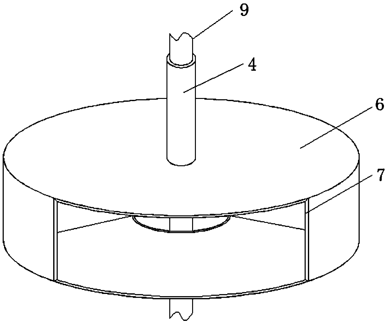
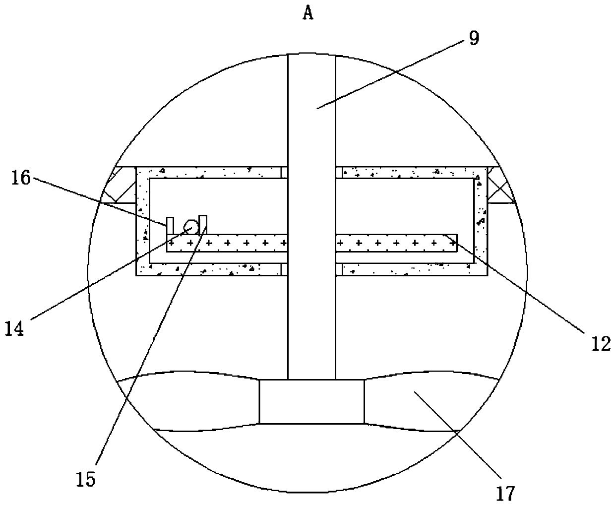
[0030] see Figure 1-5 , a hybrid heat dissipation device for outdoor power distribution cabinets using the principle of centrifugal force, including a cabinet body 1, a partition net 2, a rain shield 3, a sleeve rod 4, a wind direction plate 5, an air inlet cover 6, an air inlet 7, and a filter screen 8. Vertical rod 9, cross rod 10, wind receiving plate 11, turntable 12, control spring 13, control ball 14, contact block 15, baffle plate 16, guide vane 17, su...


PUM


Abstract

The invention relates to the technical field of power, and discloses a hybrid power heat dissipation device for an outdoor power distribution cabinet based on the centrifugal force principle. The hybrid power heat dissipation device comprises a cabinet body. A separation net is fixedly connected to the interior of the cabinet body; a flashing board is fixedly connected to the exterior of the cabinet body; the interior of the flashing board is movably connected with a sleeve rod; a wind direction plate is fixedly connected to the outer part of the sleeve rod; the bottom of the sleeve rod is fixedly connected with an air inlet cover; an air inlet is formed in the side part of the air inlet cover; a filter screen is fixedly connected to the interior of the air inlet; a vertical rod is rotatably connected to the interior of the sleeve rod; the top of the vertical rod is fixedly connected with a cross rod; the outer portion of the cross rod is fixedly connected with a wind receiving plate;through cooperative use of the wind direction plate, the wind inlet cover and the wind inlet, the wind inlet faces the wind inlet direction all the time, so that it is effectively guaranteed that natural wind fully enters the cabinet body, and the heat dissipation effect is improved.

Description

technical field [0001] The invention relates to the field of electric power technology, in particular to a hybrid heat dissipation device for an outdoor power distribution cabinet using the principle of centrifugal force. Background technique [0002] The distribution cabinet is a kind of basic equipment in the field of power equipment, which can be installed indoors or outdoors. The distribution cabinet is also called a distribution box, which generally constitutes a low-voltage forest. , Protective electrical appliances and auxiliary equipment are assembled in closed or semi-closed metal cabinets or on the screen width to form a low-voltage distribution box. During normal operation, the circuit can be connected or broken by manual or automatic switches. The power distribution cabinet mainly has two functions. : One is to distribute and control electrical equipment, and the other is to provide power-off protection when the circuit is overloaded, short-circuited or leaked. W...

Claims


Application Information

Patent Timeline
Patent Type & Authority Applications(China)
IPC IPC(8): H02B1/56H02B1/28H02B1/30H02B1/54
CPCH02B1/28H02B1/30H02B1/54H02B1/565
Inventor 柏仕海
Owner 南京博普电气成套有限公司
Why Eureka
Try Eureka