CPU radiator of mini host computer

A radiator and mini technology, applied in the direction of instruments, electrical digital data processing, digital data processing components, etc., can solve the problems of inconvenient heat dissipation, shrinking internal space, and sudden temperature rise.

Pending Publication Date: 2020-04-21
王旭宁
View PDF1 Cites 1 Cited by
  • Summary
  • Abstract
  • Description
  • Claims
  • Application Information

AI Technical Summary

Problems solved by technology

[0006] As the core of the computer, the CPU will continuously emit a large amount of heat during the computer's working process, and there will be a sudden rise in temperature during the startup process, and the ever-shrinking internal space has brought great inconvenience to heat dissipation.
The air-cooled structure is o

Method used


Image

  • CPU radiator of mini host computer
  • CPU radiator of mini host computer
  • CPU radiator of mini host computer

Examples


Embodiment 1

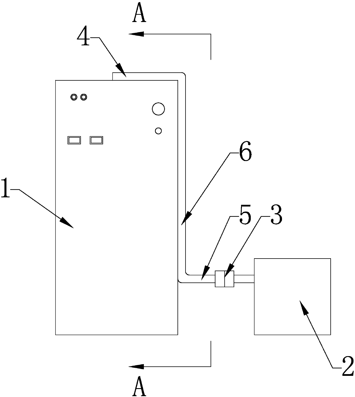
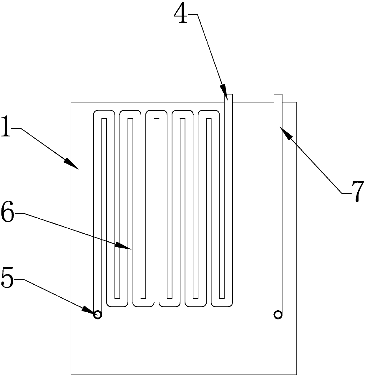
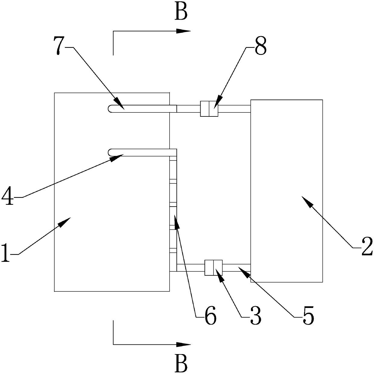
[0043] see Figure 1-Figure 7 , Figure 10 , the mini host computer CPU radiator in the present embodiment comprises:

[0044]Mini computer mainframe chassis 1 and compressor 2, CPU is located on the mainboard 9 in the minicomputer mainframe chassis 1; The CPU place in the minicomputer mainframe chassis 1 is provided with a water-cooled cooling radiator 10, is connected on the water-cooled cooling radiator 10 There is a water inlet pipe 7 and a first water outlet pipe 4; the water inlet pipe 7 passes through the mini computer mainframe chassis 1 and is connected to the compressor 2 located outside the minicomputer mainframe chassis 1, and an expansion valve 11 is arranged on the water inlet pipe 7, The expansion valve 11 is located inside the minicomputer mainframe chassis 1; a heat dissipation coil 6 is arranged outside the minicomputer mainframe chassis 1, and the first water outlet pipe 4 passes through the minicomputer mainframe chassis 1 and is connected to one end of th...

Embodiment 2

[0051] see Figure 1-Figure 5 , Figure 8-Figure 10 , the mini host computer CPU radiator in the present embodiment comprises:

[0052] Mini computer mainframe chassis 1 and compressor 2, CPU is located on the mainboard 9 in the minicomputer mainframe chassis 1; The CPU place in the minicomputer mainframe chassis 1 is provided with a water-cooled cooling radiator 10, is connected on the water-cooled cooling radiator 10 There is a water inlet pipe 7 and a first water outlet pipe 4; the water inlet pipe 7 passes through the mini computer mainframe chassis 1 and is connected to the compressor 2 located outside the minicomputer mainframe chassis 1, and an expansion valve 11 is arranged on the water inlet pipe 7, The expansion valve 11 is located inside the minicomputer mainframe chassis 1; a heat dissipation coil 6 is arranged outside the minicomputer mainframe chassis 1, and the first water outlet pipe 4 passes through the minicomputer mainframe chassis 1 and is connected to one...


PUM


Abstract

The invention discloses a mini-host computer CPU radiator. The mini-host computer CPU radiator comprises a mini-computer host case and a compressor. A water-cooling heat dissipation device is arrangedat the CPU, and a water inlet pipe and a first water outlet pipe are connected to the water-cooling heat dissipation device; the water inlet pipe penetrates through the mini computer host case to beconnected with the compressor, and an expansion valve is arranged on the water inlet pipe; a heat dissipation coil is arranged on the outer side of the mini computer host case, one end of the heat dissipation coil is connected with the first water outlet pipe, and the other end of the heat dissipation coil is connected with the compressor through a second water outlet pipe; a first separable valvegroup and a second separable valve group are respectively arranged on the second water outlet pipe and the water inlet pipe; the separable valve set comprises a first valve and a second valve, a first flange is arranged on the right side of the first valve, a second flange is arranged on the left side of the second valve, and the first valve and the second valve are hermetically connected throughflanges; cooling media are arranged in the compressor and the water pipes. The LED lamp has the advantages of being small in size and good in heat dissipation performance.

Description

[0001] (1) Technical field [0002] The invention relates to the field of computer applications, in particular to a CPU radiator for a mini host computer. [0003] (2) Background technology [0004] With the continuous development of computer technology and the continuous deepening of the miniaturization process of computers, the appearance and practical promotion of minicomputers have become an inevitable trend in the computer field. With the emergence of mini-mainframe computers, the external size of computers has been further compressed and optimized. Although this trend cannot be avoided, many problems are inevitably encountered in the process of miniaturization of computers. [0005] With the continuous deepening of the computer miniaturization process, the shape and size of the computer mainframe continue to be miniaturized. The heat dissipation caused a big problem. [0006] As the core of the computer, the CPU will continuously emit a large amount of heat during the c...

Claims


Application Information

Patent Timeline
IPC IPC(8): G06F1/20
CPCG06F1/20G06F2200/201
Inventor 王旭宁
Owner 王旭宁
Why Eureka
Try Eureka