
Electric coolant pump

A coolant pump, electric technology, applied in the direction of pumps, pump components, pump devices, etc., can solve the problems of electric coolant pump failure, failure, motor overheating, etc., to reduce heat dissipation, high mechanical pump performance, and reduce waste heat. Effect

Active Publication Date: 2021-01-22
PIERBURG PUMP TECH
View PDF6 Cites 0 Cited by
  • Summary
  • Abstract
  • Description
  • Claims
  • Application Information

AI Technical Summary

Problems solved by technology

As a result, the motor and especially the motor electronics can overheat, which can lead to malfunction or even failure of the electric coolant pump

Method used


Image

  • Electric coolant pump
  • Electric coolant pump
  • Electric coolant pump

Examples


Embodiment Construction

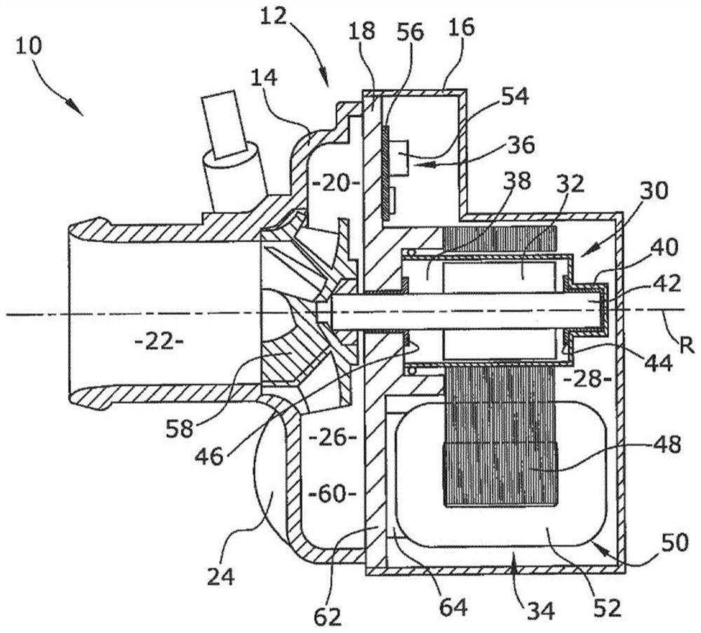
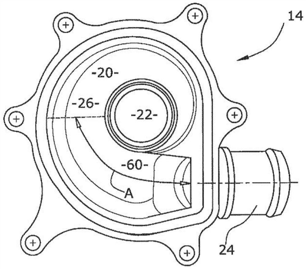
[0024] The electric coolant pump 10 comprises a multipart pump housing 12 with a pumping chamber cover element 14 , a motor chamber cover element 16 and a partition side wall 18 extending essentially in a radial plane. In the present embodiment of the invention, the partition side wall 18 is made of a material with high thermal conductivity, for example aluminum. The pumping chamber cover element 14 and the dividing side wall 18 define a pumping chamber 20 which is filled with coolant during pump operation. The pumping chamber 20 comprises a radially inner pump inlet 22 , a radially outer pump outlet 24 and a pump volute 26 extending in a radial plane from downstream of the pump inlet 22 to the pump outlet 24 . The pump inlet 22 extends substantially in the axial motor direction, and the pump outlet 24 extends substantially in a radial plane, so that the pump inlet 22 is arranged substantially perpendicularly with respect to the pump outlet 24 . The flow cross section of the ...


PUM


Abstract

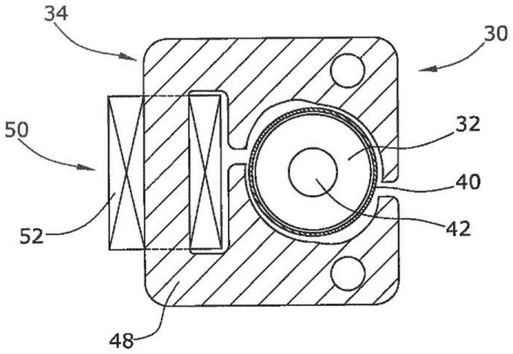
An electric coolant pump (10) comprising a pump housing (12) defining a pumping chamber (20) being filled with a coolant during pump operation, with radially Inner pump Inlet (22), a radially outer pump outlet (24) and a pump volute (26) extending from downstream of the pump inlet (22) to the pump outlet (24), and a motor chamber (28) being fluidically separated from the pumping chamber (20) by aseparation sidewal! (18) extending substantially in a radial plane, an electric motor (30) with a rotatable motor rotor (32), a static motor stator (34) with a single compact stator coil arrangement (50) being arranged laterally with respect to the motor rotor (32) in the motor chamber (28) and a motor electronics (36) being arranged in the motor chamber (28) for energizing the stator coil arrangement (50), and a pump wheel (58) being arranged in the pumping chamber (20) and being co-rotatably connected with the motor rotor (32), wherein the stator coil arrangement (50) is arranged axlally adjacent to a volute cooling sector (60) of the pump volute (26) and is in thermal contact with a cooling section (62) of the separation sidewall (18) being defined by the volute cooling sector (60) andwherein the volute cooling sector (60) of the pump volute extends over a volute angle (A) of 120 degrees starting at the pump outlet (24).

Description

technical field [0001] The invention relates to an electric coolant pump, preferably an electric coolant pump for a motor vehicle. Background technique [0002] Motor vehicle electric coolant pumps are usually provided to circulate coolant of the motor vehicle cooling circuit, mainly for cooling the internal combustion engine of the motor vehicle. To avoid damaging the internal combustion engine, electric coolant pumps must be reliable and fail-safe. Due to the limited space available in the engine compartment of motor vehicles, electric coolant pumps are usually of very compact design. An electric coolant pump can, for example, be equipped with an electric motor with a compact stator coil arrangement which requires only little space for the motor stator. However, the compact stator coil arrangement must be driven with high drive energy density to allow high mechanical pump performance. The high energy density in the stator coil arrangement generates a lot of heat, which ...

Claims


Application Information

Patent Timeline
Patent Type & Authority Applications(China)
IPC IPC(8): F04D29/58F04D13/06
CPCF04D13/064F04D29/5806F04D29/5813F04D29/5893F04D13/0626
Inventor M.赫尔米斯
Owner PIERBURG PUMP TECH
Learn More