

Wabbler mechanism of electric seat
A technology of electric seats and electric cylinders, which can be used in chairs, other seating furniture, theaters, auditoriums or similar places, and can solve the problems of large occupied area, non-environmental protection, and pollution of dynamic seats.
- Summary
- Abstract
- Description
- Claims
- Application Information
AI Technical Summary
Benefits of technology
Problems solved by technology
Method used
Image

Examples
Embodiment Construction
[0023] The present invention will be described in further detail below in conjunction with the accompanying drawings.
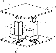
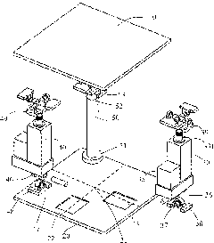
[0024] refer to figure 1 , 2 As shown, the electric seat rocking mechanism 1 of the present invention mainly includes an upper base 10, a lower base 20, a first electric cylinder 30, a second electric cylinder 40 and a support mechanism 50, wherein:
[0025] The bottom end 51 of the support mechanism 50 is affixed to the upper surface center 21 of the lower base 20, and the top end 52 of the support mechanism 50 is connected with the lower surface center of the upper base 10 through a cross universal joint 53. The support mechanism 50 can be adopted as figure 1 fixed-height support columns as shown, alternatively such as Figure 12 electric cylinder shown;
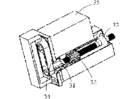
[0026] refer to image 3 , 4 As shown, the first electric cylinder 30 is mainly composed of a ball screw 31, a screw nut 32 and a lifting sleeve 33, wherein the ball screw 31 is in transmission conne...
PUM
 Abstract
Description
Claims
Application Information