Rotor gripper structure

A technology of robots and grippers, applied in the cross field, can solve the problems of unrealistic design and manufacture of universal robots, etc.

Inactive Publication Date: 2010-09-08
BEIJING UNION UNIVERSITY
View PDF5 Cites 9 Cited by
  • Summary
  • Abstract
  • Description
  • Claims
  • Application Information

AI Technical Summary

Problems solved by technology

[0002] The design of the mechanical part of industrial robots is an important part of industrial robot design. Although industrial robots are different from special equipment, they have strong flexibility, but it is unrealistic to design and manufacture universal robots.

Method used


Image

  • Rotor gripper structure
  • Rotor gripper structure
  • Rotor gripper structure

Examples


Embodiment Construction

[0017] The preferred embodiments of the present invention will be described below with reference to the drawings. In the present invention, in order to save economic cost and operation, simple design, and few design parameters, preferably, the robot gripper shown in the present invention has a rudder wheel double link structure, the specific structure of which will be described in detail later. It should be noted that it is not intended to limit the present invention, but only to illustrate the purpose of the present invention. Those skilled in the art can foresee that other structures such as V-shaped fingers, flat fingers, clamp-type and adsorption-type structures can be used.

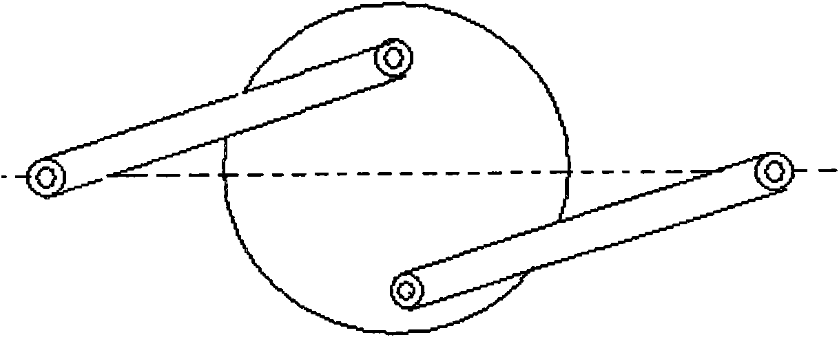
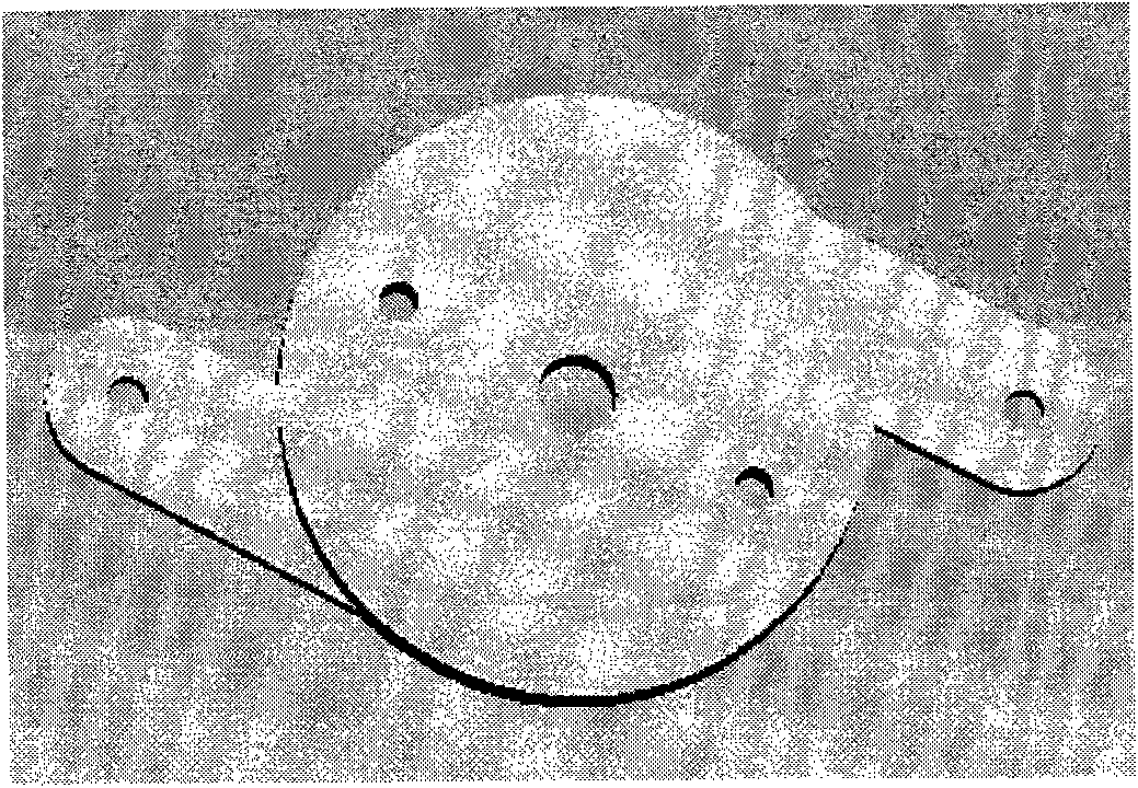
[0018] See attached figure 1 , 2 , Attached figure 1 Shows the structure diagram of the double connecting rod structure of the rudder disc, attached figure 2 Shows a real structure of a rudder disc with double connecting rods. The structure includes a circular rudder disc and two connecting rods. The t...


PUM


Abstract

The invention relates to a robot gripper structure, which comprises a circular arc finger pair, a copper column, a front baffle plate, an upper end cover, a lower end cover and a tiller double connecting rod mechanism. The tiller double connecting rod mechanism is provided with a round tiller and two connecting rods; the two connecting rods are respectively coupled to symmetrical positions on the tiller, which are certain distances away from a circle center and take the circle center as a center; fingers which are vertical to a plane where the tiller is positioned and face the same direction are arranged at handle ends of the two connecting rods respectively so as to form the finger pair for clamping a workpiece; and the center of a disk is provided with a groove gear structure which can be coupled with a corresponding projecting gear on a driving structure and drives the disk through the gear structure so as to drive the fingers on the handles at the two ends of the connecting rods to move. The robot gripper has the advantages of simple structure, low cost, and suitability for mass production.

Description

Technical field [0001] The invention relates to a robot claw structure, which belongs to the cross fields of automatic control, machinery and the like. Background technique [0002] The design of the mechanical part of the industrial robot is an important part of the design of the industrial robot. Although the industrial robot is different from the special equipment, it has strong flexibility, but it is unrealistic to design and manufacture a universal robot. The differences in the mechanical system design of industrial robots in different application fields are much larger than those in other systems of industrial robots. The hand of a robot used in industry is generally called an end manipulator. It is a part that the robot directly uses to grasp and grip (adsorb) special tools (such as spray guns, wrenches, welding tools, nozzles, etc.) for operation. It has the function of imitating human hand movements and is installed on the front end of the robot arm. Due to the differe...

Claims


Application Information

Patent Timeline
Patent Type & Authority Applications(China)
IPC IPC(8): B25J15/08
Inventor 郭洪红刘晓彤郑业明
Owner BEIJING UNION UNIVERSITY
Why Eureka
Try Eureka