
Tandem shipbuilding method for chemical tanker

A chemical tanker and shipbuilding technology, applied in ship construction, ship parts, ships, etc., can solve the problems of the center line of the hull deviate from the center line of the slipway, difficult to meet the requirements, etc., to achieve the convenience of moving the ship, improve the utilization rate and production cost. low effect

Active Publication Date: 2010-09-08
ZHEJIANG TIANSHI SHIPBUILDING
View PDF9 Cites 5 Cited by
  • Summary
  • Abstract
  • Description
  • Claims
  • Application Information

AI Technical Summary

Problems solved by technology

If the positioning is inaccurate and the center line deviates, the center line of the hull based on this center line may deviate far from the center line of the berth, which will cause a lot of inconvenience to the hoisting and closing of the subsequent sections and the measurement of the main dimensions of the hull. The secondary positioning of some sections must be able to accurately determine the correct position of the centerline and rib position in the berth, which puts forward higher requirements for the precise positioning of the stern section with large mass and volume. It is difficult for general small and medium-sized shipyards with a complete set of professional equipment to meet the requirements

Method used


Image

  • Tandem shipbuilding method for chemical tanker
  • Tandem shipbuilding method for chemical tanker
  • Tandem shipbuilding method for chemical tanker

Examples


Embodiment 1

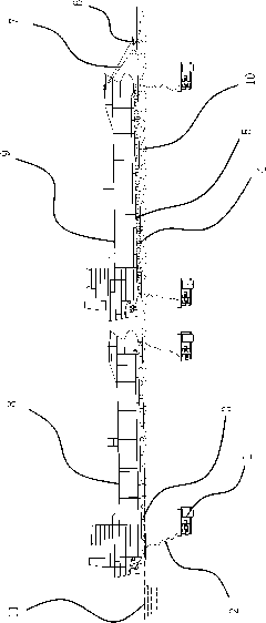
[0042] Such as figure 1As shown, the equipment involved in the present invention includes a berth 10 with a slope that can accommodate more than one ship. The berth 10 is provided with an air compressor 1 and a gantry crane, and is provided with an air bag 3 and a traction mechanism for displacement. A positioning mechanism for positioning the hull is also provided, and the positioning mechanism includes a manual jack 12, a steel pier 4, a wooden wedge 5 and a laser theodolite 13. The traction mechanism includes a winch 6 fixed on the berth 10 and positioned at the front of the bow, and a wire rope 7 is connected between the winch 6 and the hull. One end of the wire rope 7 is coiled on the winch 6, and the other end is connected with the hull, and the speed of the hull movement is controlled by controlling the release amount of the wire rope 7.

[0043] When the No. 1 ship 8 is built near the launching channel 11 at the front end of the berth 10, the stern section of the No. ...

Embodiment 2

[0051] The general content of this embodiment is the same as that of Embodiment 1, the difference is that in this embodiment, the second ship 9 only includes the stern section.

Embodiment 3

[0053] The general content of this embodiment is the same as that of Embodiment 1, and the difference is that the positioning mechanism in this embodiment includes a laser theodolite 13 positioned on one side of the hull and a steel pier 4 between the bottom of the hull and the ground, and the steel pier 4 There is a hydraulic buttress that can adjust its own height between the ship and the bottom of the hull. The hydraulic buttress includes a support with a screw that can be lifted and lowered. The screw is driven by a hydraulic device. There is a self-locking between the screw and the support. structure. The top of the screw rod is in contact with the bottom of the hull, and the bottom surface of the support is in contact with the top of the steel pier 4 . When it is necessary to position the hull section or the whole ship, at first the hydraulic support pier is placed on the steel pier 4, and the height of the hull is measured with the laser theodolite 13, and the protrusio...


PUM


Abstract

The invention provides a tandem shipbuilding method for a chemical tanker, which belongs to the technical field of ships and solves the problems of low space utilization rate, long shipbuilding period and the like in the traditional chemical tanker building process. The method of the invention comprises the following steps: A, when building No. 1 ship nearby a launching way at the lower end of a shipway, building No. 2 ship or a part of the structure of the No. 2 ship at the upper end of the shipway at the same time; B, after building the No. 1 ship, sliding the ship body to the launching way; C, moving the No. 2 ship to the place, where the No. 1 ship is primarily, at the lower end of the shipway; D, after moving the No. 2 ship to the appointed place, performing secondary positioning on the height and direction of the ship body with a positioning mechanism; and E, after positioning the No. 2 ship, continuously building the No. 2 ship, simultaneously building another ship or a part of the structure of the ship at the place where the No. 2 ship is primarily, and so on. The tandem shipbuilding method for the chemical tanker can simultaneously build more than one ship so that the production efficiency is improved.

Description

technical field [0001] The invention belongs to the technical field of ships, and relates to a tandem shipbuilding method for ships, in particular to a tandem shipbuilding method for chemical tankers. Background technique [0002] With the development of the shipbuilding industry, the segmented construction technology is becoming more and more mature. The number of segments that divide the entire ship is getting smaller and smaller, and the weight of the segments is also increasing. Most shipyards use large slipways to build ships. During the overall planning of the shipyard in the early stage of construction, the size of the slipway will be determined according to the actual construction capacity and the size of the largest ship that can be built. However, the main size of the ship usually built by the shipyard may be much smaller than the size of the slipway, and there may be many places in the slipway that are free. This creates a huge waste. [0003] The large-scale che...

Claims


Application Information

Patent Timeline
IPC IPC(8): B63B9/06
Inventor 陈佩华张华斌刘敏
Owner ZHEJIANG TIANSHI SHIPBUILDING
Learn More