Lowering and raising a single wind turbine rotor blade from six-o'clock position

A technology of wind turbines and rotor blades, applied in the field of wind turbines, can solve problems such as cost

Inactive Publication Date: 2010-09-08
GENERAL ELECTRIC CO
View PDF0 Cites 14 Cited by
  • Summary
  • Abstract
  • Description
  • Claims
  • Application Information

AI Technical Summary

Problems solved by technology

Significant expenses are incurred when renting, acquiring, operating and moving large cranes

Method used


Image

  • Lowering and raising a single wind turbine rotor blade from six-o'clock position
  • Lowering and raising a single wind turbine rotor blade from six-o'clock position
  • Lowering and raising a single wind turbine rotor blade from six-o'clock position

Examples


Embodiment Construction

[0091] The following embodiments of the invention have many advantages, including allowing wind turbine rotor blades to be replaced without the need for large, expensive heavy lifts. The method further allows removal and replacement of the rotor blades with simple equipment in a manner that protects the blades from damage. Blade straps are provided which distribute the weight over a substantial length of the rotor blade during lifting and provide protection for the trailing edge from damage during lifting.

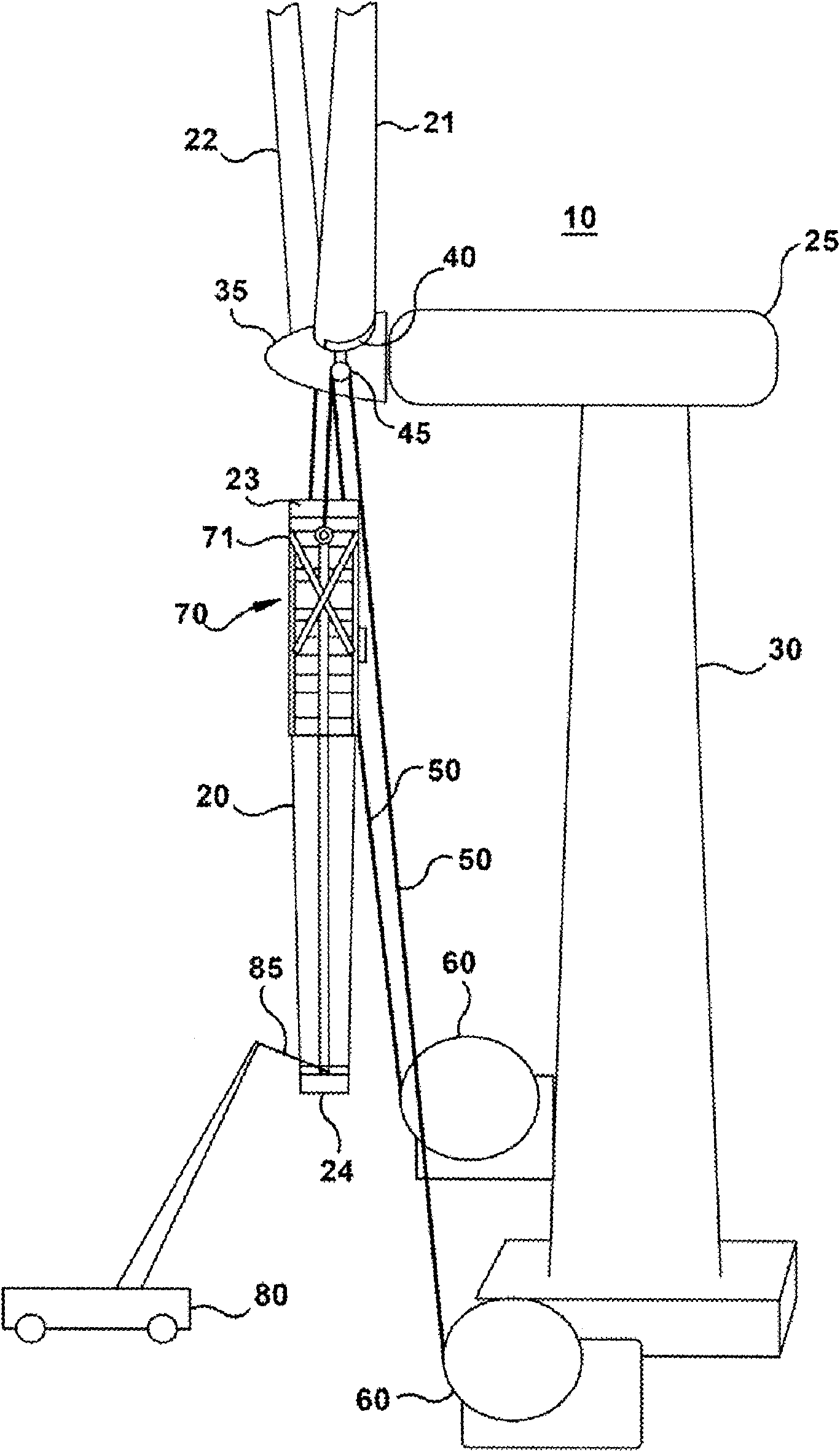
[0092] figure 1 A simplified representation of one embodiment of an arrangement for lifting and removing a rotor blade from a six o'clock position on a rotor hub of a wind turbine tower is shown. A lifting arrangement 10 is provided for lifting a rotor blade 20 mounted in the six o'clock (vertical hanging) position. Nacelle 25 is positioned on top of wind turbine tower 30 and houses wind turbine power generation equipment (not shown) connected to rotor hub 35 . Three ro...


PUM


Abstract

An arrangement 200 and method for lowering and raising a single rotor blade 305 of a wind turbine 30 from a six-o'clock position is provided. Lifting fixtures 240, 245 are symmetrically attached on a rotor hub 235 at pitch bearing flanges for rotor blades 225, 230 about the rotor blade 305 being replaced. Lifting lines 270, 275 from coordinated ground winches 60 pass over the lifting fixtures 240, 245 to support the blade 220, attaching to a blade harness 300. The blade harness 300 attaches over a substantial length of the rotor blade 220, distributing the blade weight broadly. A tail pick crane 80 facilitates transfer of the rotor blade 220 between a vertical position and a horizontal position stored position.

Description

technical field [0001] The present invention relates generally to wind turbines and, more particularly, to apparatus and methods for lowering and raising wind turbine rotor blades from the six o'clock position. Background technique [0002] The rotor blades are attached to the rotor hub of the wind turbine at the rotor hub flange. The rotor blades may be mounted to the rotor hub flange during the initial installation of the wind turbine. The rotor blades may need to be removed and replaced during the lifetime of the wind turbine. Rotor blades may need to be replaced due to damage from environmental causes such as lightning strikes, rust and hail, or from physical stress or defects within the blades. [0003] Wind energy is becoming an increasing source of electrical power both domestically and internationally due to the environmental demand for a clean, non-CO2 generating energy source. Taller wind towers with larger and heavier rotor blades are being produced to more eff...

Claims


Application Information

Patent Timeline
Patent Type & Authority Applications(China)
IPC IPC(8): B66C25/00B66F19/00F03D1/06F03D1/02F03D11/00
CPCF03D1/001Y02E10/728Y02E10/721F03D13/10Y02E10/72Y10T29/37Y10T29/49318
Inventor B·P·里德T·O·康弗斯S·H·奥尔森M·R·约翰森
Owner GENERAL ELECTRIC CO
Why Eureka
Try Eureka