Method of and system for hauling a marine equipment unit, a marine equipment unit and a carrier

a marine equipment and carrier technology, applied in the field of marine equipment and carrier hauling methods and systems, can solve the problem that the auv may easily crash into the hull of the carrier

Inactive Publication Date: 2018-11-15
FUGRO NV
View PDF18 Cites 8 Cited by
  • Summary
  • Abstract
  • Description
  • Claims
  • Application Information

AI Technical Summary

Benefits of technology

[0004]In view of the above, it is an object of the present invention to provide a recovery method for hauling marine equipment back onboard a carrier, that can be performed independent of the weather conditions, e.g. even at rough weather and sea conditions or at wind forces above 5 Beaufort.
[0006]The method of the invention uses marine equipment that releases or launches a hauling buoy connected to two lines: a tow line and a lift line. The tow line is then used for towing the marine equipment unit towards the carrier, while the lifting line is connected to an additional winch (i.e. the second winch) that is used for providing an additional force on the lifting point of the equipment unit to enable guiding thereof during hauling onboard. The hauling may be performed with help of a hauling ramp installed on the carrier, or the equipment unit may be hauled directly on board the carrier. The carrier may be a vessel, e.g. a survey ship, or any other water based carrier, such as an offshore platform or structure. The equipment unit, e.g. an AUV, may now more easily be prevented from crashing onto the carrier or, in case a hauling ramp is used, accidentally end up underneath the hauling ramp. Close to the carrier, under influence of high or violent waves, the AUV may easily crash into the hull of the carrier. Additional guidance provided by means of the second winch, or even a controlled operation of the first and second winch, enables to prevent undesired contact between the equipment and any part of the carrier. Thereby, the method of recovering the equipment unit of the present invention can be performed under rough conditions at sea.
[0007]In accordance with some embodiments, the guiding of the equipment unit during the hauling step is performed by operating the second winch such as to maintain tension in the lift line exerted onto said lift point. Even without actually lifting the marine equipment unit out of the water, enough tension can be applied via the second winch to better control the movement of the unit in the water. For example, the nose of an AUV can be lifted upward to prevent it from ending up underneath the ramp. As another example, pulling the lifting point of the AUV will aid in maintaining it balanced and aligning the AUV in front of the ramp. This thereby allows to safely haul the marine equipment unit onto the hauling ramp.
[0009]The suspension structure may for example be an A-frame, launch boom or even an onboard crane. In this respect, it is noted that an A-frame or launch boom including a telescopic arm negates the height disadvantages of such structures as compared to cranes, while providing simplicity, stability and strength. Moreover, A-frames are more commonly available on existing vessels than cranes.
[0016]In accordance with embodiments thereof, the suspension structure comprises an extendable and retractable telescopic arm suspending from an in use upper part of the suspension structure, wherein a guiding structure is connected to an end of the telescopic arm, wherein the guiding structure is arranged for receiving the marine equipment unit for aligning thereof in a preferred alignment direction during hauling. The advantages of these embodiments have been described above. Alternatively, in accordance with some embodiments, the suspension structure comprises a slidable beam, wherein the second winch is installed on the slidable beam. By providing a slidable beam that extends at a sufficient height (e.g. 2 or more meters above the deck to allow passing underneath) parallel to the deck of the ship, the second winch can be used for example to lift the nose of an AUV such as to haul it onto the hauling ramp without crashing of the nose into the ramp.

Problems solved by technology

Close to the carrier, under influence of high or violent waves, the AUV may easily crash into the hull of the carrier.

Method used


Image

  • Method of and system for hauling a marine equipment unit, a marine equipment unit and a carrier
  • Method of and system for hauling a marine equipment unit, a marine equipment unit and a carrier
  • Method of and system for hauling a marine equipment unit, a marine equipment unit and a carrier

Examples


Embodiment Construction

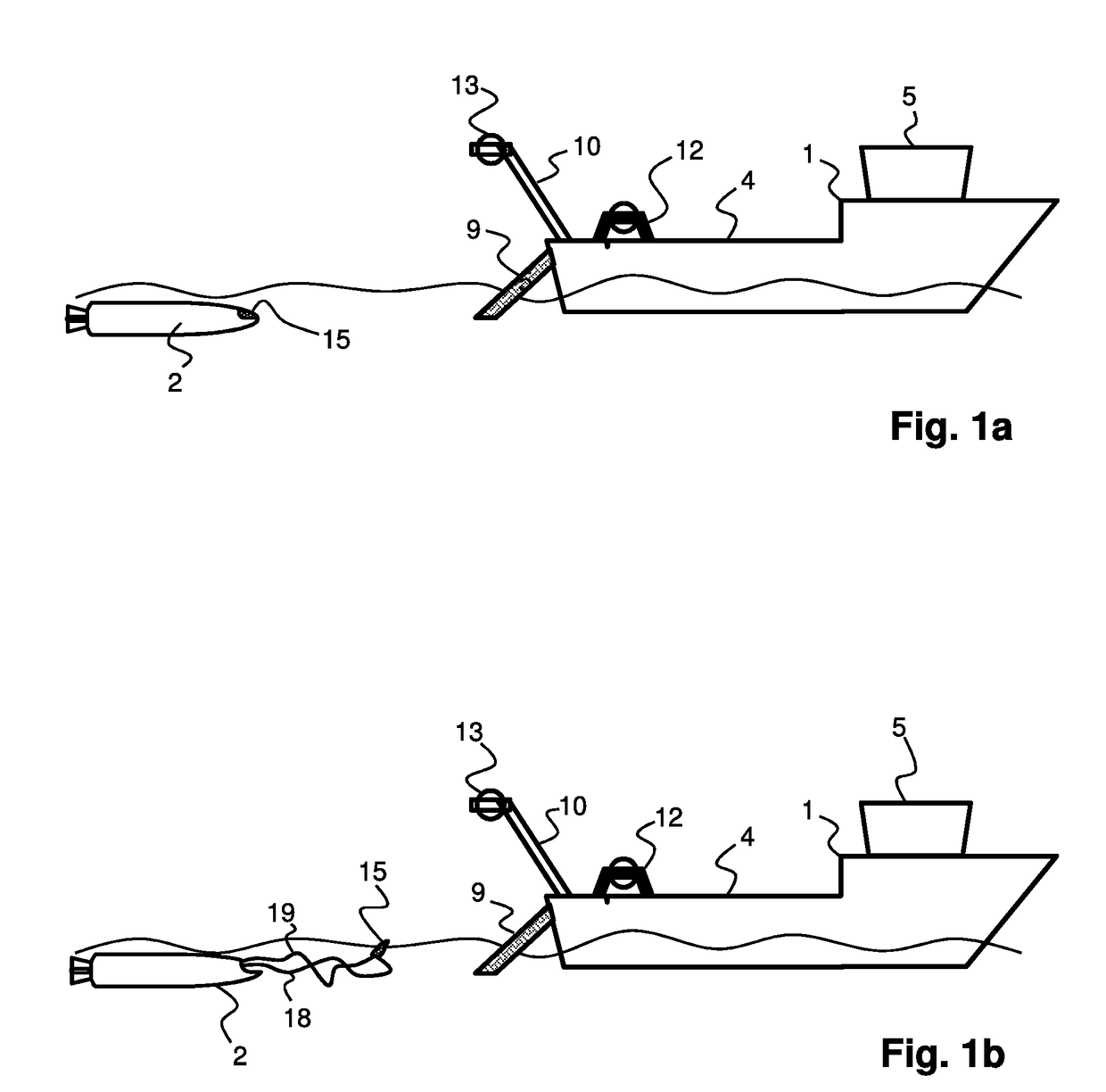
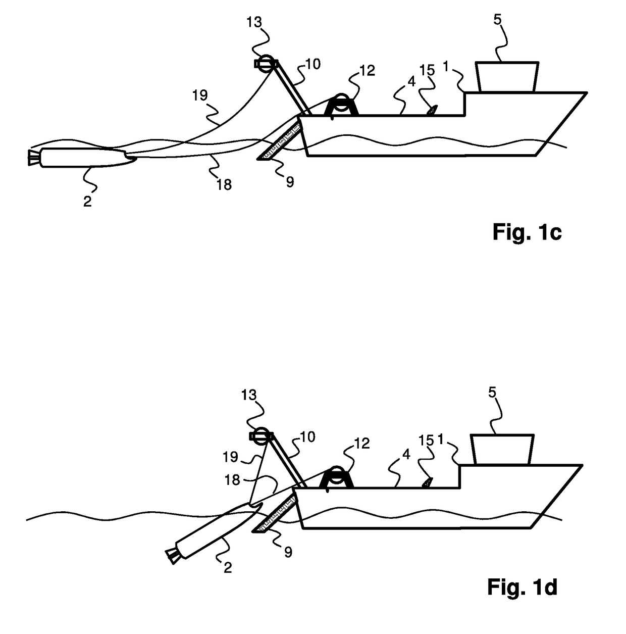
[0025]FIGS. 1A through 1D schematically illustrate a method in accordance with the present invention, for hauling an equipment unit 2 from the water onto a vessel 1. The vessel 1 has installed thereon a system for hauling equipment units such as autonomous underwater vehicles (AUV's) 2 for recovery. Autonomous underwater vehicles such as equipment unit 2 can be used for a variety of different tasks, amongst which are investigation and survey of the sea floor. For example, an AUV 2 may be used search for mining locations, wreckage, geological underwater structures (e.g. volcanoes, abysses, etc.). Other tasks that may be performed using an AUV is to perform seismic surveys of sub-bottom structures, such as to find possible locations of oil and gas fields. Moreover AUV's may be applied for all kind of defensive tasks.

[0026]To perform these tasks, the AUV 2 comprises a variety of sensor units, communication units, processing means and other sensitive equipment, which may easily be damag...


PUM


Abstract

The present document describes a method of hauling an equipment unit from the water onto a carrier. The carrier comprises a hauling ramp, which is arranged for being extended from a loading area into the water. The carrier further includes a first winch, and a suspension structure arranged for being extended outside the carrier over the water and over the hauling ramp. The suspension structure comprises a second winch. The method comprising the steps of: releasing, by the equipment unit, a hauling buoy. The hauling buoy is connected to a tow line extending from the equipment unit, and to a lift line extending from a lifting point on the unit. The method comprises a further step of recovering the hauling buoy from the water, connecting the tow line to the first winch and connecting the lift line to the second winch. Then, the equipment unit is hauled by towing it onto the hauling ramp using the first winch, while simultaneously guiding the equipment unit using the second winch. The method is in particular useful for hauling of an autonomous underwater vehicle (AUV) during bad weather conditions at sea. The document also describes the equipment unit and a system for hauling that can be installed on a carrier, as well as a carrier comprising such a system.

Description

FIELD OF THE INVENTION[0001]The present invention is directed at a method of hauling an equipment unit from the water onto a carrier. The invention is further directed at a marine equipment unit, at a marine equipment hauling system for use onboard a carrier and at a carrier comprising such a system.BACKGROUND[0002]The present invention is in particular directed at the hauling of marine equipment onboard a vessel or other water based carrier under rough marine conditions, such as high seas and strong winds. A large variety of underwater sensor and survey systems is nowadays used for performing many different tasks. One class of equipment is for example formed by autonomous underwater vehicles (AUV's) that are used for survey of the sea bed, e.g. to search for mining locations, wrecks, or other features, or to map the bottom surface structures or subsurface structures and elements. Such AUV's are often equipped with sensitive and costly sensor equipment, such as interferometric sonar...

Claims


Application Information

Patent Timeline
Patent Type & Authority Applications(United States)
IPC IPC(8): B63B27/36
CPCB63B27/36B63B2027/165B63G2008/005B63G2008/004B63G8/42B63B27/16
Inventor PASTOR, CHADKINNEAR, STEPHENSONNIER, CARLTHAME, ALICK NEILSCHOLTENS, MARCO
Owner FUGRO NV
Why Eureka
Try Eureka