Micro-operation type valve
A valve and micro-manipulation technology, applied in the direction of lift valve, sliding valve, valve device, etc., can solve the problems of wasting energy, difficult operation, affecting the appearance of the environment, etc., and achieve the effect of reducing production cost, saving metal materials, and avoiding equipment failure.
- Summary
- Abstract
- Description
- Claims
- Application Information
AI Technical Summary
Problems solved by technology
Method used
Image

Examples
Embodiment 1
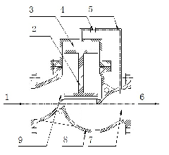
[0041] Such as figure 1 As shown, the micro-operated valve of the present invention comprises an inlet chamber 9, a buffer chamber 3, and an outlet chamber 7, and the buffer chamber 3 is arranged between the inlet chamber 9 and the outlet chamber 7, and the above-mentioned three parts are connected by the valve core 2 The chamber is opened. A medium passage is provided between the buffer chamber 3 and the outflow chamber 7, and a control valve 4 is provided on the medium passage. The medium passage is set as a pressure guiding pipe 5 connected between the buffer chamber 3 and the outflow chamber 7 , and the control valve 4 is arranged on the pressure guiding pipe 5 .
[0042] Working principle: The medium enters the inlet chamber 9 from the inlet 1. When the control valve 4 is closed, the pressure between the inlet chamber 9 and the buffer chamber 3 is balanced due to the gap between the valve core 2 and the valve cover. Under the action of the pressure difference between th...
Embodiment 2
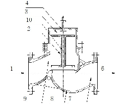
[0045] Improvements are made on the basis of Embodiment 1, that is, a through hole 10 is provided in the center of the valve core 2, the medium passage is set in the through hole 10 in the center of the valve core 2, and the control valve 4 is set above the buffer chamber 3 and the valve core 2. A valve sealing relationship is formed between the spool 2 of the control valve 4 and the spool of the large valve.
[0046] According to the above principle, when the control valve 4 is opened, the large valve is opened; when the control valve 4 is closed, the large valve is closed. The benefits of such improvements are:
[0047] The integration of large and small valves simplifies the structure and installation workload, but the disadvantage is that the stroke of the operating valve is the same as that of the large valve. If the operating valve is electric or pneumatic, the requirement for the stroke of the actuator is slightly higher.
Embodiment 3
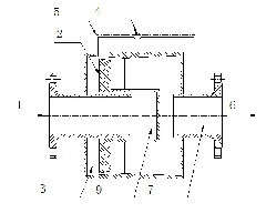
[0049] In this embodiment, the flow of the traditional stop valve is changed, and the structure of the medium flowing vertically through the valve port is changed to axially flowing.
[0050] The medium enters the inlet chamber 9 from the inlet 1. When the control valve 4 is closed, refer to the description of the implementation case 1, the pressure between the inlet chamber 9 and the buffer chamber 3 is balanced, and the large valve is closed; when the control valve 4 is opened, the buffer chamber The pressure of 3 is close to the pressure of the outlet chamber 7, and under the action of the pressure difference between the inlet chamber 9 and the buffer chamber 3, the spool 2 moves to the left to open the large valve. This valve can be called: axial flow micro-operated valve. The advantages of this valve are: 1. The flow of the medium is smoother than that of the traditional globe valve, so the flow resistance is small and energy-saving; 2. The appearance is simple and beauti...
PUM
 Abstract
Description
Claims
Application Information
PatSnap Eureka turns technology decisions into work you can execute. Powered by our Innovation Knowledge Graph, it runs expert workflows across engineering, life sciences, materials and intellectual property. Get your review-ready output in minutes.


