
Heat dissipation-optimized LED (light-emitting diode) lamp and light fitting thereof

A technology of LED lamps and LED lamps, applied in lighting and heating equipment, components of lighting devices, cooling/heating devices of lighting devices, etc., can solve the problems of unreasonable design of heat sinks, high cost, large product size, etc.

Inactive Publication Date: 2010-09-08
秦彪
View PDF7 Cites 6 Cited by
  • Summary
  • Abstract
  • Description
  • Claims
  • Application Information

AI Technical Summary

Problems solved by technology

However, professionals in the LED industry and the electronics industry do not have a very clear understanding of the natural convective heat transfer in the finned heat sink, lack of targeted basic research, and do not know the fins in the heat sink. The impact of height and gap on heat dissipation results in: unreasonable heat sink design, no optimized design concept, large product size, heavy weight, and high cost. For example: 100W LED street lights, the heat sink uses more than ten kilograms of aluminum, Some even use high-cost heat pipe technology

Method used


Image

  • Heat dissipation-optimized LED (light-emitting diode) lamp and light fitting thereof
  • Heat dissipation-optimized LED (light-emitting diode) lamp and light fitting thereof
  • Heat dissipation-optimized LED (light-emitting diode) lamp and light fitting thereof

Examples


Embodiment Construction

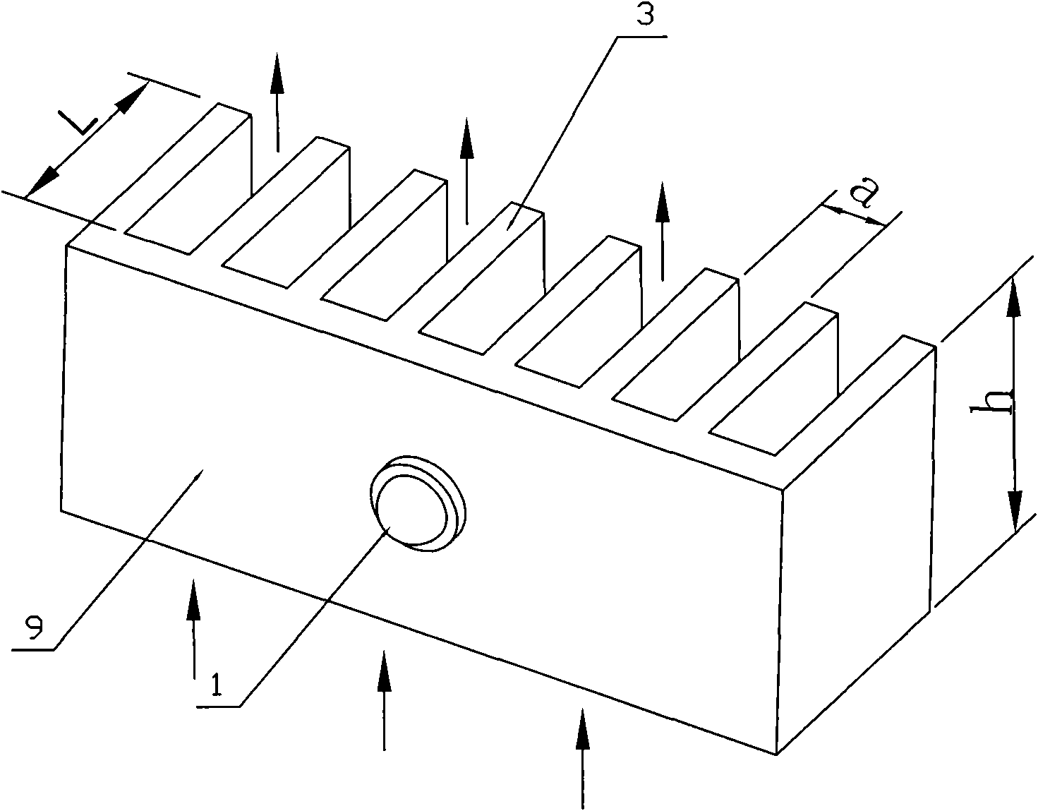
[0031] figure 2 In the LED lamp shown, the LED core 1 is arranged on the side of the heat-conducting block 9, the fin 3 extends from the other side of the heat-conducting block 9, and the length L of the protrusion is the length of the fin. In the figure, the heat conduction block 9 is erected, and the fins 3 are also erected. The arrows in the figure indicate air flow. In natural convection, the air passes through the fins 3 from bottom to top. The height h of the fins is the direction in which the air passes through the fins. The gap a between the fins is the space distance between two adjacent fins.

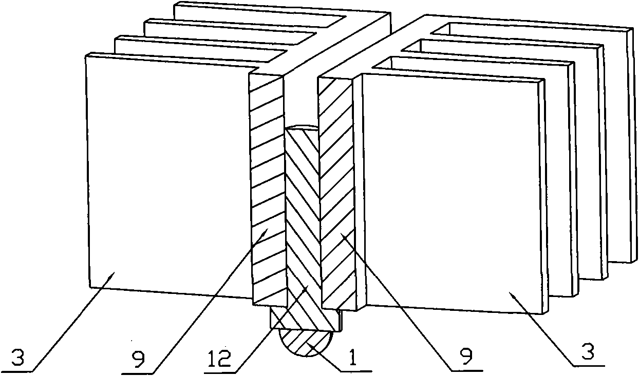
[0032] image 3 In the LED lamp shown, the LED core 1 is arranged on the lower end surface of the thermally conductive block 9 with two heat sinks. The thermally conductive core 12 of the LED core 1 is sandwiched by the thermally conductive blocks 9 of the two heat sinks, and the heat of the LED wick 1 passes through the thermally conductive core 12 Transfer to the heat conducti...


PUM

PropertyMeasurementUnit
Average clearanceaaaaaaaaaa

Abstract

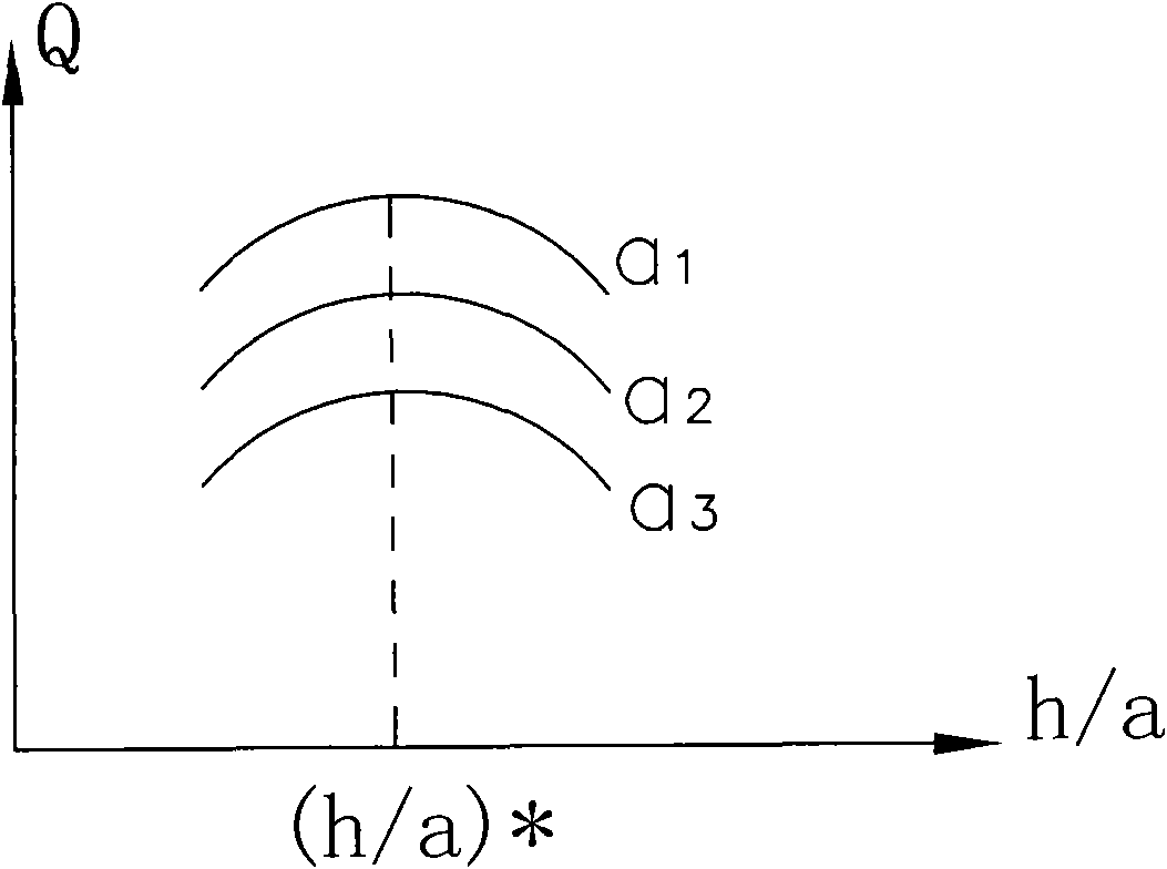
The invention provides an LED lamp with an optimized radiating fin dimension and structure according to the natural convection heat transfer basic experiment research results aiming at fin-type structures, which points out that the ratio of the height h of fins to the gap a between the fins is not more than 10.0, and the gap a is not less than 1.7mm. The heat dissipating capacity is further increased by additionally installing a convection shield (4), and thereby, the level that the aluminium consumption of heat dissipation per watt is less than 4g can be achieved. In order to realize standardization, a radiating fin is separated from an LED lampwick comprising an LED core (1) and a heat conduction core (12), wherein the radiating fin is a component fixed in a light fitting, and a specific scheme for solving the heat transfer problem between the heat conduction core (12) and the radiating fin is proposed.

Description

Technical field [0001] The invention belongs to the technical field of LED lighting, and particularly relates to the optimized design of the structure and size of the heat sink in the LED lamp. technical background [0002] LED lighting has attracted global attention due to its energy saving and long life, and is considered to be the next generation of lighting technology. However, the heat dissipation problem is a major obstacle in the development of today's LED lighting technology, and it accounts for a considerable part of the cost of the LED lamp, and restricting the popularization and application of LED lighting is the high cost of the entire lamp. Natural convection heat transfer, no mechanical movement, no noise, high reliability, is a must-choice method for LED heat dissipation. However, professionals in the LED industry and the electronics industry do not have a very clear understanding of the natural convection heat transfer in the fin structure of the heat sink, lack ...

Claims


Application Information

Patent Timeline
IPC IPC(8): F21S2/00F21V29/00F21V17/00F21V19/00F21Y101/02F21V29/508F21V29/71
Inventor 秦彪
Owner 秦彪
Learn More