Apparatus and foam electroplating process

a technology of electroplating process and apparatus, which is applied in the direction of electrolytic process, current insulating device, electrolytic device, etc., can solve the problems of depletion of electrolyte inside the foam structure, difficulty in uniform electrodeposition, etc., and achieve the effect of increasing the mass transport of electrolyte and reducing current density

Inactive Publication Date: 2007-12-06
INCO
View PDF12 Cites 27 Cited by
  • Summary
  • Abstract
  • Description
  • Claims
  • Application Information

AI Technical Summary

Benefits of technology

[0013]An apparatus for electroplating foam is provided which includes a container, an anode and a cathode, wherein the anode and the cathode are located within the container, the anode including at least one metal for plating the cathode, the cathode including a polymeric foam including an electrically conductive material, wherein the cathode is oriented at an angle of about 1 degree to about 45 degrees relative to vertical. The cathode may be a continuous foam strip which is fed into the container, routed past the anode and out of the container by one or more guides. In the presence of a solution containing an electrolyte, the angle of the cathode causes a diagonal convection current of the solution through the foam, thereby increasing mass transport of electrolyte into the interior of the foam. In one embodiment, the anode is in a substantially vertical orientation within the container. In another embodiment, the anode is canted. In one embodiment, there are first and second anodes and the foam is positioned between the first and second anodes. In one embodiment, the anodes and cathode have respective ends where electrical current is applied, and the distance between the cathode and at least one of the anodes is greater at the ends where electrical current is applied than at opposite ends where current is not applied. In one embodiment, the anode and cathode have respective ends where electrical current is applied, and a porous non-conducting current limiting mask is positioned between the anode and the cathode for reducing current density between the anode and the cathode.

Problems solved by technology

Uniform electrodeposition is made difficult by the three-dimensional character of the foam and the nature of electrodeposition which can inhibit plating inside the structure.
This is because the plating process inside the foam may be limited by the rate of the mass transport controlled by slow diffusion of metal ions into the inside structure of the foam.
If the current density and total plating rate is too high relative to the rate of the diffusion process, the electrolyte inside the foam structure becomes depleted.
Metal deposition then becomes inefficient, and the deposit porous and of poor quality.
The resulting product is less plated in the middle than on the outside and has inferior mechanical and corrosion characteristics.
It is difficult, for the reasons mentioned above, to obtain a DTR of 1:1.
At that point, hydrogen ion discharge becomes prevalent, lowering the current efficiency of metal deposition.
Metal deposited near or at this so-called limiting current may be of extremely poor quality, i.e., very porous and with entrapped electrolyte.
Unfortunately, mechanical agitation is not as uniform as natural convection so the deposition rate becomes less uniform as well.
Plating a three-dimensional structure such as foam is further complicated by electrolyte depletion inside the foam, where natural convection flow is severely inhibited.
The pores inside the foam are a fraction of a millimeter across—comparable to the diffusion layer thickness—making the convective exchange of the depleted electrolyte with the bulk electrolyte extremely poor.
Low electrolyte concentration inside the foam reduces electrochemical efficiency of plating and aggravates the non-uniform deposit thickness.
However, this method can be difficult to control.
Forced flow produced by pumping or agitation is typically not sufficiently uniform over the whole surface and also tends to distort the shape (flatness) of the plated area.
Densities of foam will then reflect the local flow velocities and distances from the anode, becoming non-uniform over the surface.
In most battery applications, non-uniform foam density is unacceptable as it causes premature battery failure in battery packs.
Because of the difficulties with non-uniform plating under forced convection conditions, metal foam is frequently produced under natural convection.
Vertical plater geometry provides short distance between the contacts and the plated area—an important factor considering that all plating energy has to be supplied via the plated foam, and that foam conductivity is limited even at full product density leaving the plater.
Unfortunately, vertical foam orientation does not provide effective natural convection into the foam, and this can lead to poor density distribution throughout the foam thickness.
Such systems are inherently more complex, involve poorly accessible nickel baskets beneath the foam, and are generally more difficult to operate and maintain.
However, electrolytic foam technologies share a common problem, i.e., inability to operate at a uniform current density matching the capability of mass transport.
As a consequence, foam quality can be negatively affected by exceeding safe current density in the top zone, while most of the plater operates far below its productivity potential.
Accordingly, various electrolytic foam technologies involve the same compromise between productivity and quality.

Method used


Image

  • Apparatus and foam electroplating process
  • Apparatus and foam electroplating process
  • Apparatus and foam electroplating process

Examples


Embodiment Construction

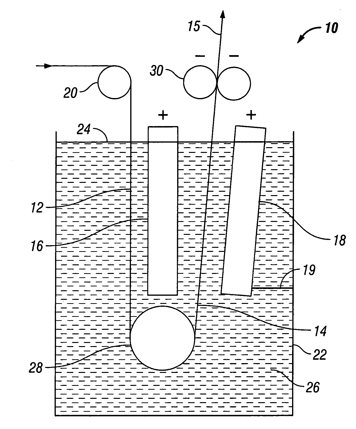
[0021]Optimization of natural convection through the interstices of a foam matrix results in a more efficient electroplating process and a metal foam having more uniform deposition of metal throughout its structure. Accordingly, the techniques disclosed herein advantageously allow increased strength of the finished material, as well as more uniform surface and interior structure, increased tensile strength, dimensional stability, wear resistance, and corrosion resistance.

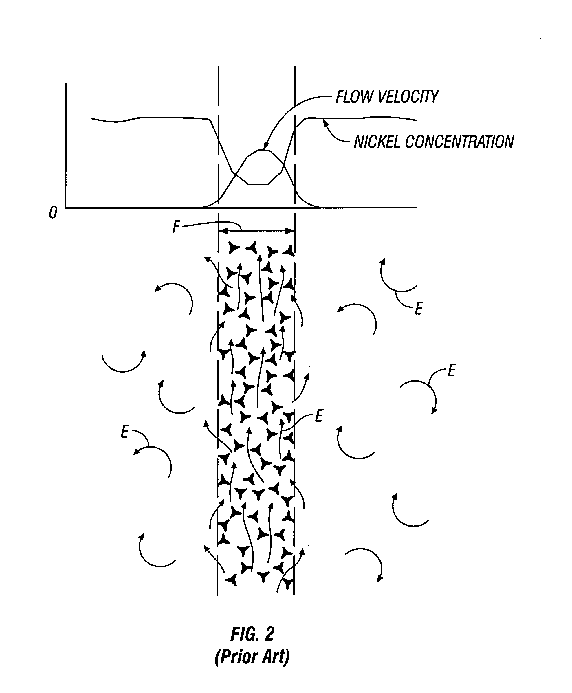
[0022]Natural convection of electrolyte solution through the interstices of a foam matrix is optimized during electroplating by inclining or tilting the foam cathode in a plater. FIG. 3 schematically illustrates laminar flow of electrolyte through an inclined foam cathode F′. Electrolyte motion and currents are depicted as arrows E′. As electrolyte solution contacts the cathode F′, as can be seen from the mass transfer graph, electrolyte is depleted in the area closest to the foam F′, leading to a zone of lower dens...


PUM

PropertyMeasurementUnit
angleaaaaaaaaaa
thickaaaaaaaaaa
thickaaaaaaaaaa

Abstract

An improved apparatus and method of producing metal foam is provided which involves optimizing the natural convection of electrolyte through a foam being electroplated by inclining the foam during plating. A diagonal flow of electrolyte though the foam enhances electrolyte turnover within the foam while increasing electroplating efficiency. Further increases in plating efficiency are provided by shifting current density from higher plating zones to lower plating zones.

Description

TECHNICAL FIELD[0001]The present invention relates to metal plated foams in general and to apparatus and methods for manufacturing them in particular.DESCRIPTION OF RELATED ART[0002]Metal foams, such as nickel foam, are well-known and used, for example, in making electrodes for batteries. Metal foam is a highly porous, open cell, metallic structure based on the structure of open-cell polymer foams. Metal foam may be produced by electroplating. To produce a metal foam such as nickel foam, nickel metal may be coated onto open-cell polymer substrates such as polyurethane foam and sintered afterwards to remove the polymer substrate in a controlled atmosphere at high temperature. A typical process can start with long strips of polyurethane foam, for example, between about 1-2 mm thick and about 1 m wide. The polyurethane strip can be made electrically conductive by coating, e.g., with a conductive carbon ink, by pre-plating with nickel using an electroless deposition, or by a vacuum sput...

Claims


Application Information

Patent Timeline
Patent Type & Authority Applications(United States)
IPC IPC(8): C25D3/12C25C7/02
CPCC25D1/08C25D5/04C25D5/08C25D17/008C25D7/0614C25D7/0642C25D17/10C25D7/04C25D1/00C25D3/12C25D5/56
Inventor ETTEL, VICTOR ALEXANDER
Owner INCO
Why Eureka
Try Eureka