A solid adsorbent regenerating device and an adsorption device applying the regenerating device

A technology of solid adsorbent and regeneration device, applied in the field of adsorption, can solve the problems of low temperature, easy carbon deposition on the heating surface, low thermal conductivity, etc., and achieve the effects of simple structure, reduced heat loss and high thermal efficiency.

Inactive Publication Date: 2017-04-19
GUANGDONG UNIV OF TECH
View PDF37 Cites 29 Cited by
  • Summary
  • Abstract
  • Description
  • Claims
  • Application Information

AI Technical Summary

Problems solved by technology

[0013] (1) Hot air purge regeneration method: activated carbon will be oxidized by air after heating, so each heating regeneration will cause an oxidation loss of about 3% to 5% of the weight of activated carbon
Moreover, when the regeneration heating temperature is improperly controlled, the activated carbon bed is easy to catch fire in the hot air
In addition, deflagration may occur when the organic vapor generated by the desorption of organic adsorbates mixes with the hot air for regeneration. Therefore, a large amount of regeneration air flow must be used to dilute the organic vapor, resulting in the emission of a large amount of tail gas at a temperature of about 100 °C.
[0014] (2) hot nitrogen purge regeneration method: it needs to consume a lot of nitrogen
[0017] The disadvantages of the partition heating regeneration method are: (1) The temperature of the heating surface of the regeneration heater must be lower than the heat-resistant temperature of the solid adsorbent
(2) The heating surface of the regenerative heater is prone to carbon deposition, and the powder

Method used


Image

  • A solid adsorbent regenerating device and an adsorption device applying the regenerating device
  • A solid adsorbent regenerating device and an adsorption device applying the regenerating device
  • A solid adsorbent regenerating device and an adsorption device applying the regenerating device

Examples


Embodiment 1

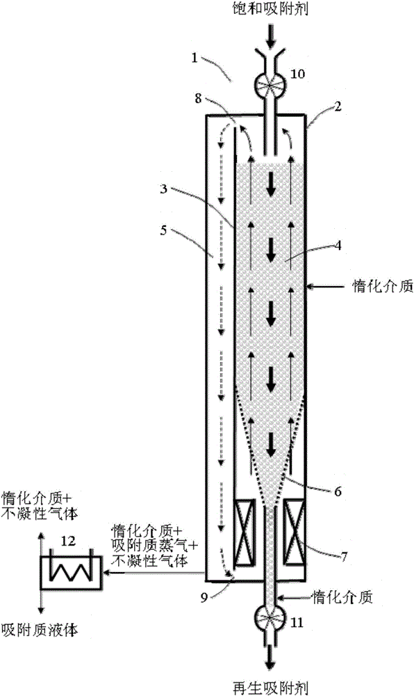
[0063] Such as figure 1 As shown, it is a structural schematic diagram of a regeneration device internally divided into two parts according to the present invention. see figure 1 , regeneration device 1 has furnace body 2, and its inside is divided into two parts by partition wall 3, and wherein one part is adsorbent bed 4, and another part is vertical gas flow channel 5, and the upper space of adsorbent bed 4 and the lower space and vertical The upper space and the lower space of the air flow channel 5 communicate through the upper vent 8 and the lower vent 9 respectively. Sorbent bed 4 bottoms are supported by ventilating funnel 6 (the shape of this ventilating funnel 6 is adapted to body of heater 2, and ventilating funnel 6 walls are provided with many apertures, and the diameter of these apertures is less than adsorbent particle diameter, makes ventilating funnel 6 The walls allow the gas to pass through, but not the adsorbent particles). Ventilation funnel 6 below is ...

Embodiment 2

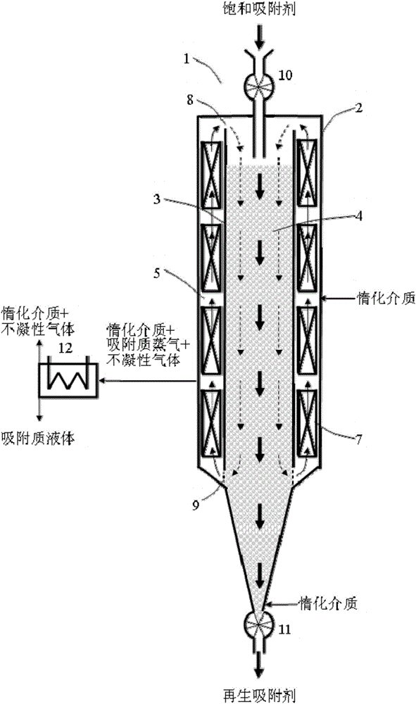
[0114] Such as figure 2 As shown, it is a structural schematic diagram of a regenerative device internally divided into three parts according to the present invention. see figure 2 , The regeneration device 1 has a furnace body 2, and its interior is divided into three parts, one of which is provided with an adsorbent bed 4, and the other two parts are provided with a series of regeneration heaters 7. The part where the adsorbent bed 4 is located is the cold side, and the part where the regeneration heater 7 is located is the hot side. The heating of the regenerative heater 7 makes the gas on the hot side flow upwards, and the gas on the cold side flows downwards, forming a circulation flow of the gas inside the regeneration device 1, transferring the heat of the regenerative heater 7 to the adsorbent bed 4, and making the adsorbent Regenerated by heating. figure 2 The thick solid line arrows in the device indicate the moving direction of activated carbon during the rege...

Embodiment 3

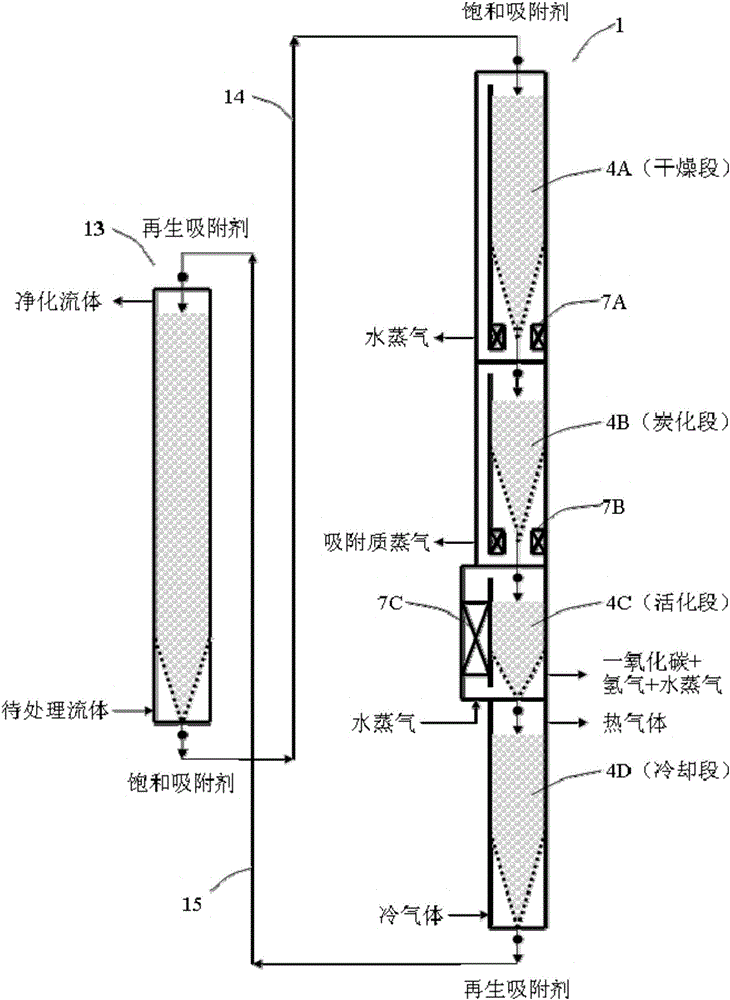
[0118] This embodiment is a multi-stage regeneration device, which is mainly used for the regeneration of liquid-phase adsorption activated carbon (such as waterworks activated carbon). see image 3 , The regeneration device 1 consists of four sections: the activated carbon moving bed 4A is the drying section, 4B is the carbonization section, 4C is the activation section, and 4D is the cooling section. 7A, 7B, and 7C are heaters for the drying section, the carbonization section, and the activation section, respectively. The structure of each section is the same as that of the regeneration device 1 described in Embodiment 1 (there is one difference: in the activation section, the heater 7C is arranged in the vertical air flow passage 5).

[0119] When the device is in normal continuous operation, the saturated adsorbent is added from the top of the regeneration device 1, and after passing through each section of the moving bed, the regenerated adsorbent is discharged from the ...


PUM

PropertyMeasurementUnit
Boiling pointaaaaaaaaaa
Porosityaaaaaaaaaa

Abstract

A solid adsorbent regenerating device and an adsorption device applying the regenerating device are disclosed. The regenerating device includes a regenerating heater and an absorbent bed. The regenerating device is configured in a manner that heating by the regenerating heater allows gas in the regenerating device to circularly flow between the regenerating heater and the adsorbent bed, and heat provided by the regenerating heater is transferred through the circular airflow to the adsorbent bed so that an adsorbent is heated and regenerated. According to one embodiment, the inside of a furnace body of the regenerating device is divided into two parts, top ends of the two parts are communicated with each other, bottoms of the two parts are communicated with each other, and the regenerating heater is in one of the two parts. The adsorption device applying the regenerating device is also disclosed. Circular heating in a natural convection manner is utilized to regenerate the solid adsorbent. The regenerating device and the adsorption device have advantages of low consumption of inert gas, no or extremely low waste emission, a high heat efficiency, simple equipment, a low cost, and the like.

Description

technical field [0001] The invention relates to the technical field of adsorption, in particular to a regeneration device for a solid adsorbent and an adsorption device using the regeneration device. Background technique [0002] Adsorption is a gas-solid or liquid-solid two-phase interface chemical phenomenon. When a gas or liquid is in contact with a solid surface, one or several components in the gas or liquid accumulate on the solid surface. This phenomenon is called adsorption. . The adsorbed substance is called adsorbate, and the adsorbed solid is called adsorbent. According to the difference in the force between the adsorbent surface and the adsorbate, adsorption can be divided into physical adsorption and chemical adsorption. The adsorption mainly caused by the van der Waals force between the adsorbate molecules and the adsorbent is called physical adsorption. The adsorption of adsorbate on the surface of the adsorbent mainly through the exchange of valence electr...

Claims


Application Information

Patent Timeline
IPC IPC(8): B01J20/34B01D53/02C02F1/28B01D15/00
CPCB01D15/00B01D53/02B01D2253/102B01D2257/30B01D2257/602B01D2257/708B01J20/3416B01J20/3483C02F1/283C02F2303/16
Inventor 黄海涛
Owner GUANGDONG UNIV OF TECH
Why Eureka
Try Eureka